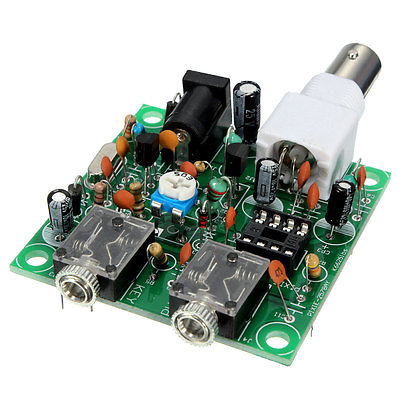
The Pixie is a fun and popular QRP transceiver kit. However, typical output power on 40 M is only about 300 to 500 milli-Watts – a bit too QRPp at times…
In this article I’ll show cheap and easy ways to pump up the output power to around 1.2 or over 2 Watts, depending upon the power supply type and crystal activity.
 UPGRADE THE OUTPUT STAGE TRANSISTOR
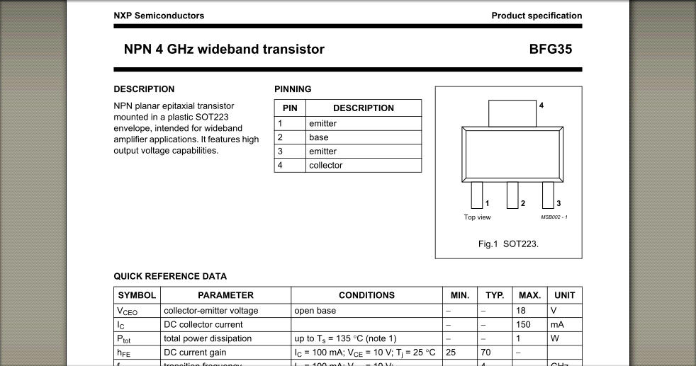
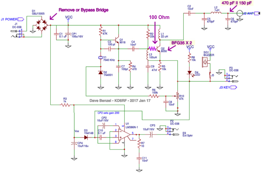
The first modification uses 3 components – 2 x BFG35 transistors in parallel (soldered to a small homebrew copper heat sink) to take the place of the output 2N2222, and a 150 pF capacitor to parallel the existing output capacitor. Note that there are several versions of the Pixie, so the value of the new paralleled capacitor may have to be empirically determined.
Total cost of components is less than $3 from the usual electronics suppliers such as DigiKey, Mouser, Newark, etc…
 On my unit, existing components are on a non-plated-through circuit board, making standard component removal procedures difficult. The easiest method of removing the 2N2222 was simply to clip it’s leads and push the stubs through the board with soldering iron and the new resistor and solid wire risers. The resistor and solid wire risers are left in place in order to connect to the new transistors; both sides of the board should be soldered.
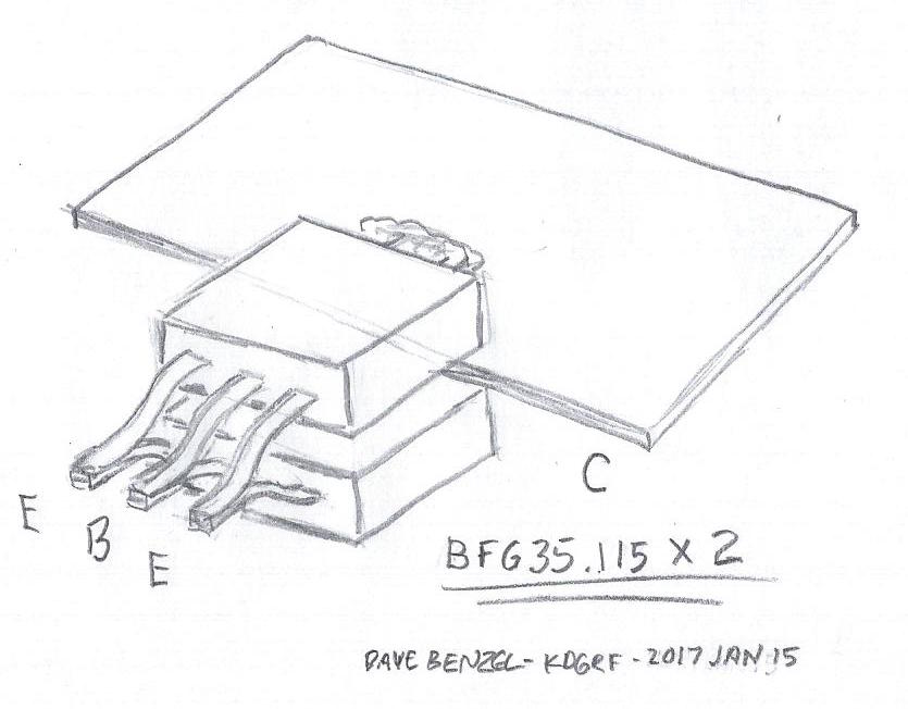
In preparation for installation, the new transistors are paralleled and soldered to a small “scissor-ware” copper sheet heat sync (i.e. cut with scissors) as shown ===>
 The BFG35 transistor stack is soldered to the risers, in place of the 2N2222. Note the 100 ohm 1/8 watt resistor in series with the base connections to enhance crystal stability ===>
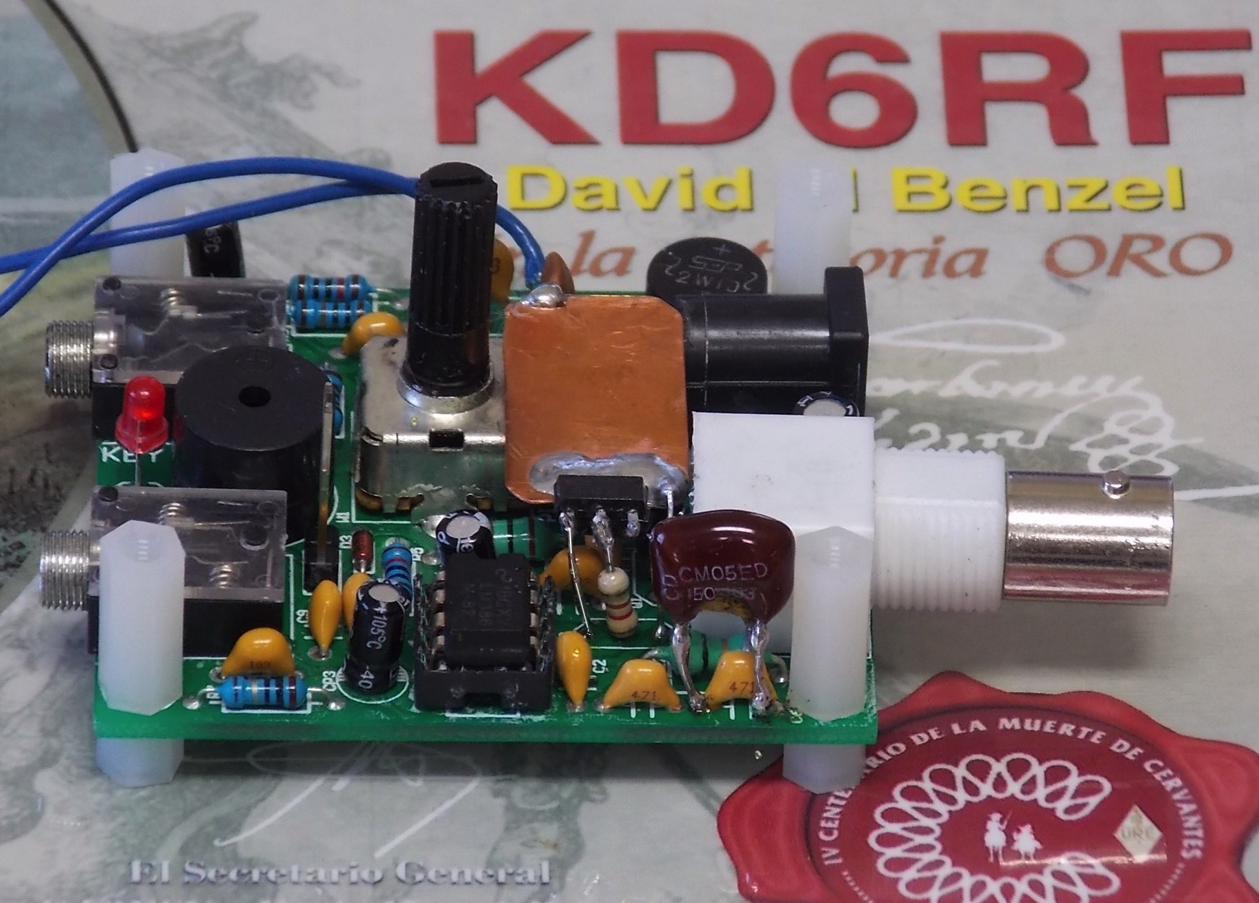
Also note that on the far side of the copper heat sink, I soldered in a small value capacitor (a high value resistor could also be used) to ground for mechanical stability of the transistor stack and heat sink. Now, parallel in the new 150 pF capacitor across the pi-network output capacitor, and that’s it for this mod.
Output power and overall efficiency for this mod alone ended up at 1.2 Watts / (0.19 Amp x 13.5 Volts) = 47%
A final modification can be made to pick up another 10 or 20% power output by changing C7 to 39 pF or so. The risk with mod is that some weaker crystals may not start up reliably.
POWER SUPPLY BRIDGE RECTIFIER
In some versions of the Pixie, such as my units, a bridge rectifier is used in the power supply feed to protect the circuitry and presumably allow for operation on AC.
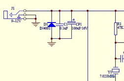
This, of course, uses up 2 diode-drops = 1.4 Volts of VCC which significantly reduces output power. Wire directly to the power source instead of going through the bridge, and output power can pop up to over 2 Watts with a good crystal! It would be a good idea to add a hefty reversed diode, like the bottom schematic, to protect the circuitry.
 When this mod is added to the transistor mod above, typical output power and overall efficiency ended up at about 2.0 Watts / (0.27 Amp x 13.5 Volts) = 55%.
Naturally, output power increases even more, to around 2.5 Watts or more, if the supply is taken up to the 14+ Volts available with car power systems. Conversely, if you want to retain the spirit or QRPp at the commonly defined 1 Watt level, you can run the Pixie on a 9 Volt battery and be putting out around 1 Watt, which is still close to an S-Unit better than the original.
My units are run on 12.5 Volt internal lithium-ion batteries with an auxiliary power of 13.4 Volt lead acid battery. To run at the 1 Watt informal QRPp power level, I limited the output of my units to right around 1 Watt by increasing the value of the base resistor.
No time was spent optimizing – it may very well be the case that more power and higher efficiency can be attained with a bit more consideration. In the mean time, enjoy that S-Unit or more increase in power!
Copyright Dave Benzel – KD6RF – 2017-Jan-17
25,136 total views, 5 views today
I am interested in having these mods performed on a 40m pixie I ordered tonight. What would you charge me to perform the”operation” on my pixi
Thanks for this! I’m a little confused about the transistors in parallel. Do the Emitters of each transistor get joined together, the Collectors joined together, and Bases joined together?
The image shows Emitters on each side and Base in the middle, but is that the Collector at the plate? And also, if the transistors were mounted on the heatsink (like in the image) then the Emitter of one transistor would be linked to the Collector of the other. Confused.. I want to try this… just want to do it correct..
You can look up the transistors – you will see that the tab is C, the two outer terminals are E, and center is B.
I was surfing the web today to see if there was a good output amp for my Chinese pixie. But after looking at this mod, I was curious to see if this is the max power that can be achieved for these pixie’s? Crazy as it sounds, I’d like to see if there was a way of making the output selectable in 1, 2, 3, 4, and 5 watt output steps. Any ideas?
Thanks