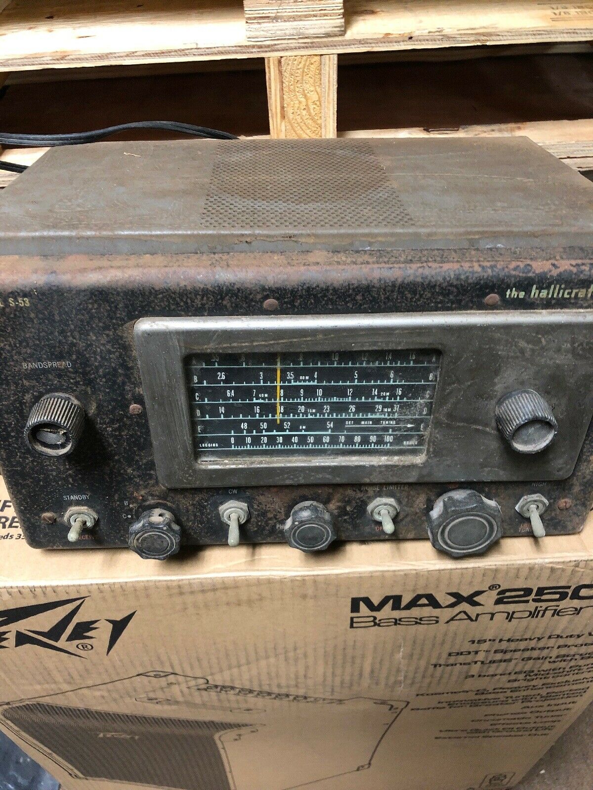
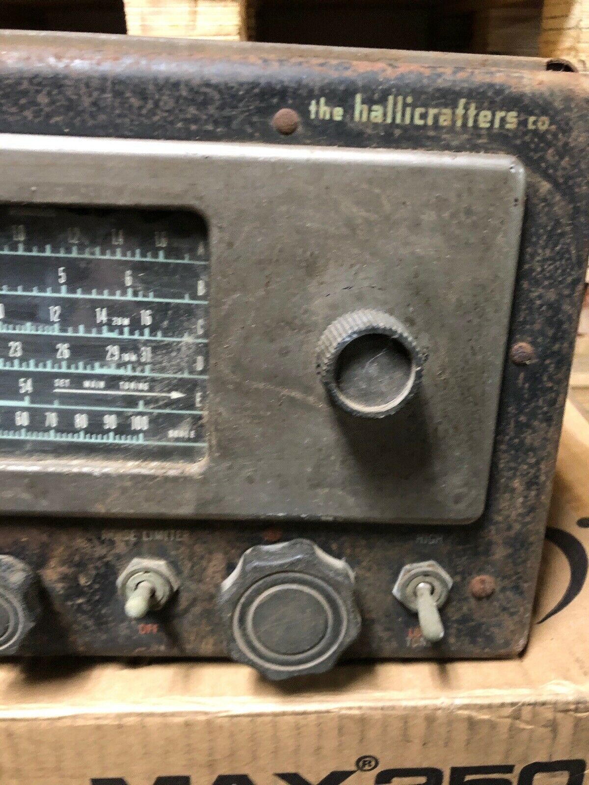
I really like the classics, the glow of tubes and smell 🙂 of transformers And having a short window of free time decided to pick up a poor ugly semi-rusted Hallicrafters S-53 for cheap. I was interested in it’s somewhat unusual 2.075 MHz IF frequency (used to enhance image rejection). I decided to try out a weird idea in regard to not really restoring, but rather quickly resurrecting an old not-so-valuable boat anchor.
Before:
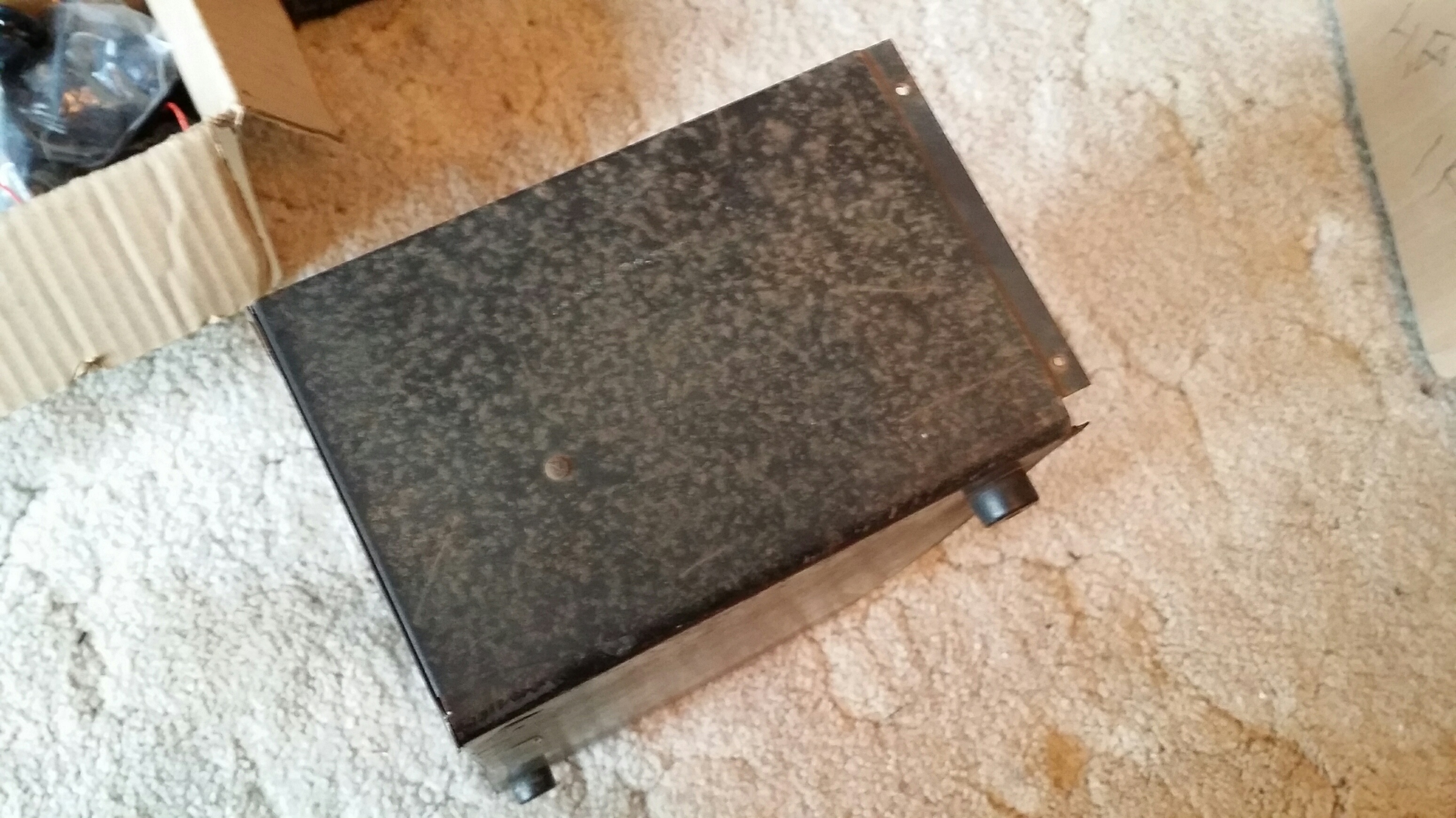
PHYSICAL RESURRECTION: The weird idea was – use RIT black dye to blacken the surface rust and presumably make the unit visually acceptable. I applied dye directly to the lightly scuffed and cleaned black surfaces, making sure to leave the lettering intact and dye-less. In the first pic, you can see the dyed area, with un-dyed rusty metal to either side. Next 2 pics are before and after dying the side metal of the radio cabinet.

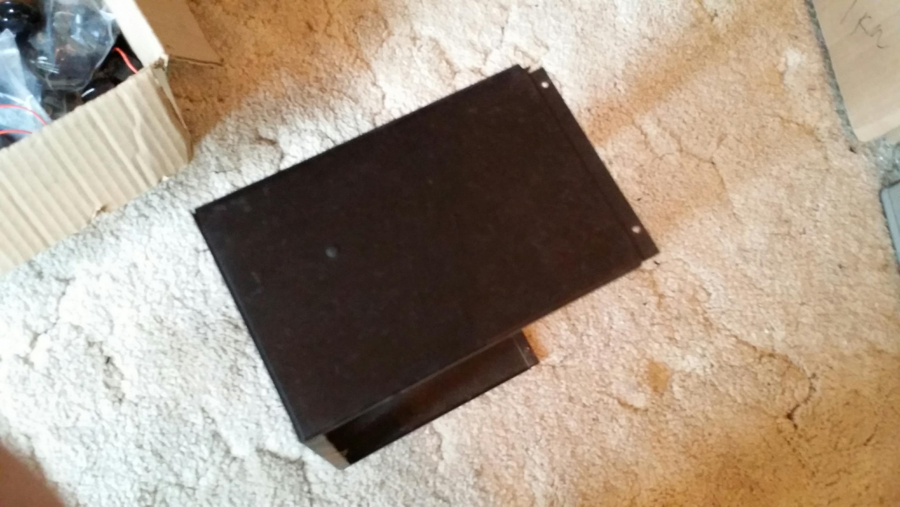
I think it worked well – the black portions of the radio now look okay (from afar). It’s “handsome” and now looks like a decent but well used old radio that’s still doing it’s job.
After:

At any rate you can judge for yourself if you think that this is a quick and useful technique to get an otherwise worthless cheapo radio back into service J
I also re-painted the non-rusted surfaces as well as replaced and painted the missing knobs with similar ones.
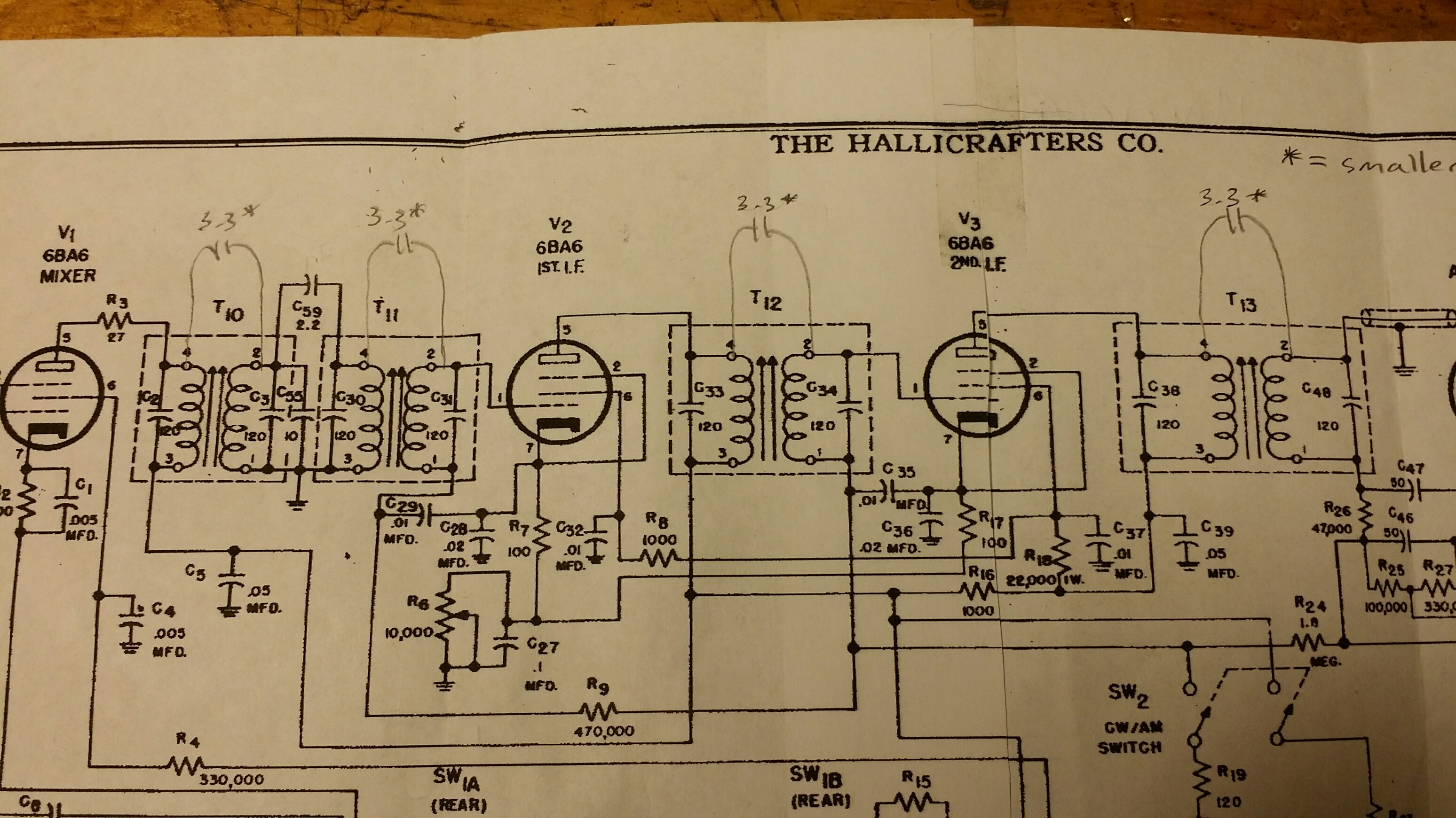
ELECTRONICS RESURRECTION: This was one dead son of a gun. After a careful re-cap job, it was still dead as a doorknob. After troubleshooting, I found that the 2.075 MHz IF transformers suffered from uncorrectable mis-tuning. Inside, I found that Hallicrafters built in a weird custom-ish silvered mica stack located under an insulator stack at the bottom of the unit.
I cleaned out the crud and silvered-mica flakes, and re-installed with external capacitors. I had some good vintage silvered-mica discrete units, as well as some small 1 KV ceramic NPO’s.
Dang thing STILL was dead – hardly any response at all to RF. I could see (on the scope and by ear at speaker output) that the IF transformers were now tuning correctly, but sensitivity to RF was about 1 freekin Volt required to get audio out. W3IRD…
Tracing signal with the o-scope showed signal was magically being lost when going through the IF transformers – even though they tuned correctly and matched the schematic. SOOOooooo, I took a leap and guessed that Hallicrafters left out of the schematic some coupling capacitors that were part of the internal destroyed silvered mica stacks.
I do that myself sometimes with my schematics for equip I design in order to keep the unethical project thiefs in a state of confusion 🙂
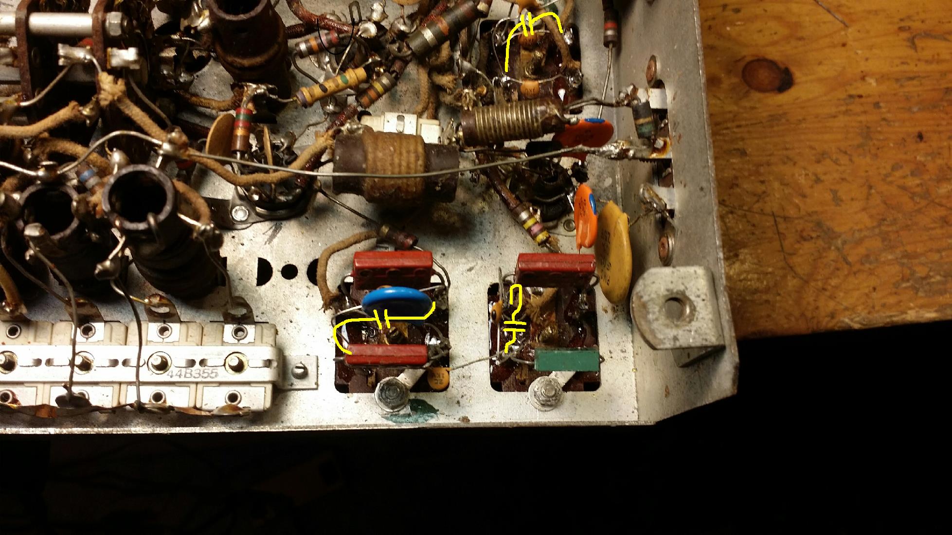
BINGO – apparently those crumbled silvered mica stacks had a built-in coupling cap from top to bottom resonator. I found that an approx 3.3 pF, now external to the transformers, provided the best sensitivity / selectivity compromise. You can see the external 120 pF tuning caps across each “transformer” (left to right), and harder to see are the 3.3 pF resonator coupling caps, highlighted in yellow:
I replaced the damaged speaker with an inexpensive 4×6 unit from eBay, and this is now one of the better sounding units in my collection.
copyright Dave KD6RF
4,217 total views, 2 views today