Having a few nice vintage shortwave radios around, I decided it would be nice to actually USE the dang things once in a while 🙂 And given the almost unusably noisy performance of indoor short wire antennas, I made some loop antennas to cover approx 3 – 18 MHz to see if performance could be enhanced.
The short answer is: Yes, performance is enhanced – for my noise environment (many computers and cable TV) this small loop allowed me to partially null some noise sources, and in general pulls more shortwave stations out of the noise than the typical 10 ft wire. Shortwave listening most days and night is now fun again.
BASIC MECHANICAL DESIGN
Nothing ground breaking here. I no doubt saw at some time various frame type antenna that looked to be easy to build. I did some experiments with cardboard boxes as coil forms to see how small I could make the loop, and how many turns were required.
The result is that I ended up using 4 turns for response down to 3 MHz or so, and 2 turns (switched) for response up to around 18 MHz. The loop configurations are tuned using common eBay 365 pF tuning caps.
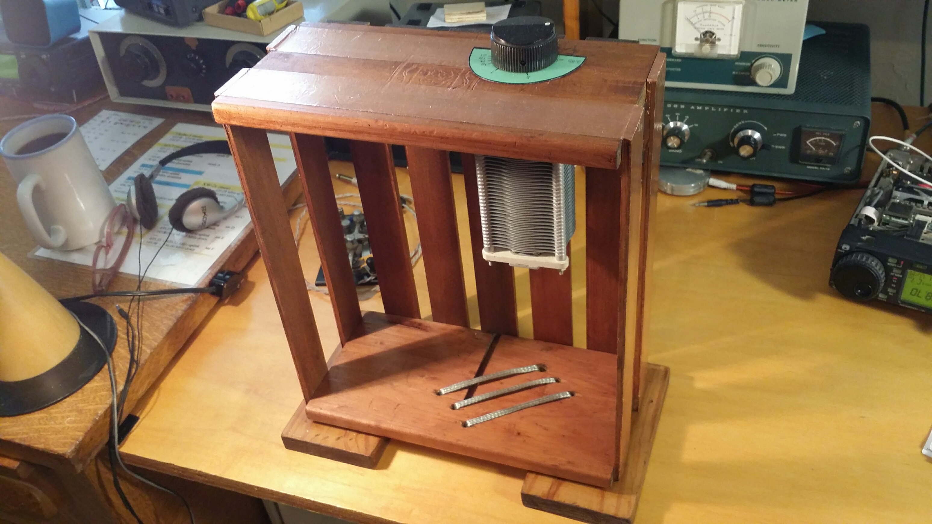
The X-frame boards are 2 3/4 inches wide, and 14 1/2 inches long, slit half way across 1/2 inch higher than center. This allowed me to have some “feet” below the wire loops to keep them from intimate contact with the underneath surface. As you can see below, the wire fits into filed grooves at the board tops, and is threaded through holes drilled into the board bottoms 1/2 inch from the ends.
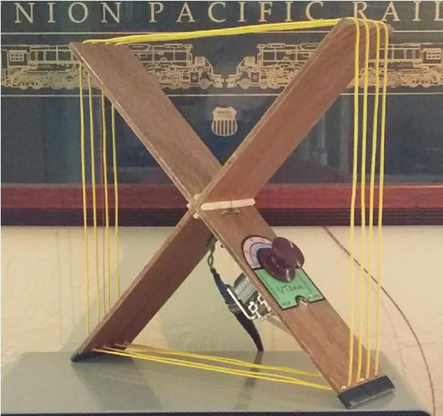
Regular wood glue or Elmers glue on the slits holds everything together. I added some cut-up match sticks to the junctions for strength, but I don’t think this was really required.
WIRING
The dual band unit switches in 2 or all 4 turns of the loop. This is the schematic:

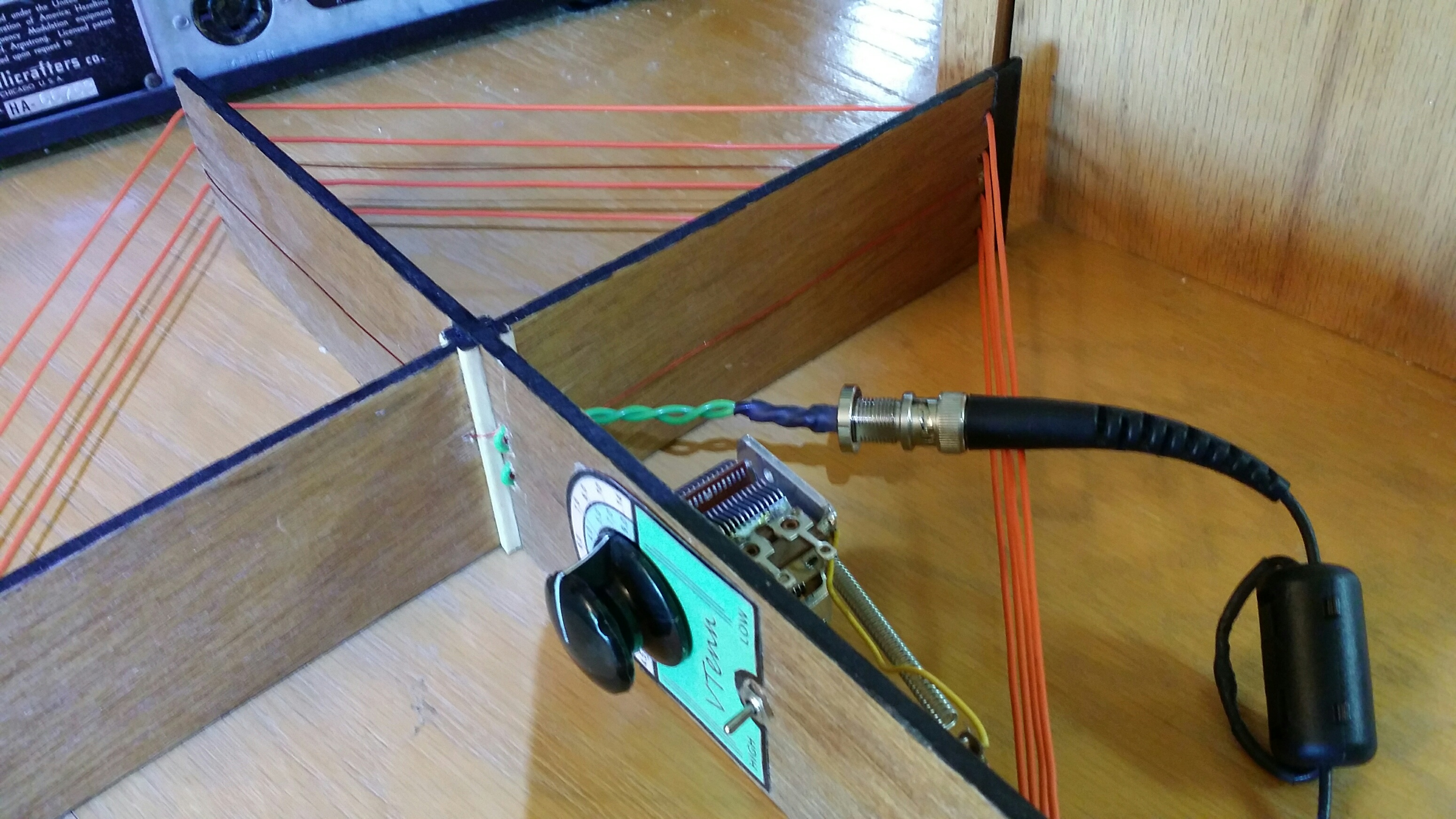
Note that I used springs to keep the loop reasonably taught. Interestingly, it turns out that the steel of the spring quite strongly attenuated signal strength (efficiency) !! As a quick test, I loaded up a loop and drove it with a few Watts on 40 M. I was surprised to see that one spring started smoking, started getting red, and subsequently lost it’s temper. 😮 That’s why you see wires soldered ACROSS the springs in the pix.

The coupling loop was guessed at (got pretty close) and trial-and-errored into a size that gave a decent match to 50 ohms on both high and low bands over the entire range. As you can barely see, the coupling loop is small red magnet wire encompassing 1/4 (one quadrant) of the frame, and is directly connected to a BNC connector. Some semblance of balance is retained with the few-turn choke (type 43 material) on the interconnecting coax.
TUNING
With the loop size shown above of # 18 wire, tuning was sharp but usable. To aid in setting the dial, I drew up a frequency scale, as well as switch legend for the two bands. You can download the pdf below if desired.
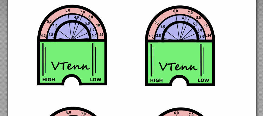
Small-4-turn-loop-antenna-dial.pdf
I printed and laminated these “dial plates” with my super nifty laminating machine 🙂 Every one should know the joy of laminating 🙂
EFFICIENCY
Pretty much everything in the radio world comes down to efficiency. For RX use, it is more often called “sensitivity”, or some other label, but it’s really efficiency as a transducer of EM waves to a matched 50 output that counts.
In words, this loop is more than efficient (or sensitive) enough for in-door noisy-environment usage. If one desires better performance, we would have to get the loop antenna outside away from noise – in which case we would likely have to increase the loop size / efficiency. 1 Meter diameter is generally a ball park size for a usable out-door loop that allows reception down to the noise floor, but this varies greatly upon location.
Anyway, what is the ACTUAL efficiency of this loop? I did some simultaneous WSPR tests of this antenna compared to an approx 0 dBi Inverted-L. I was just barely able to drive the loop with 5 watts before the tuning cap arced. Data for 20 Meters was measured:

28 dB DOWN – UHG !! I did not bother measuring other bands – it’s clear that efficiency gets worse as one goes down in frequency 🙁
Quite usable for SWL, but eexxttrreeeeeemellyy inefficient as a TX antenna.
VARIATIONS
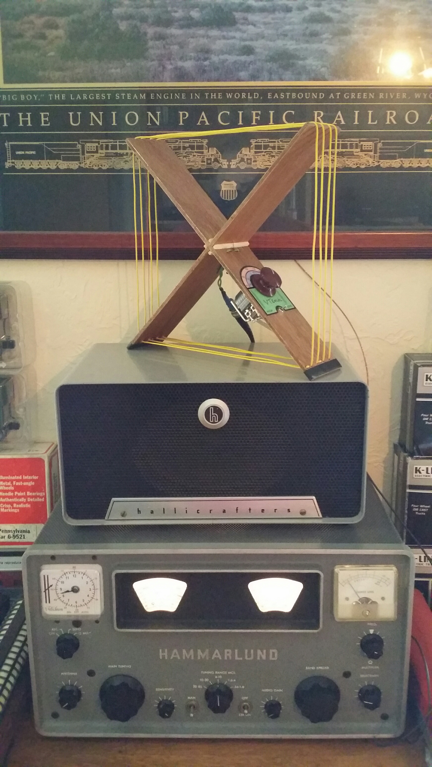
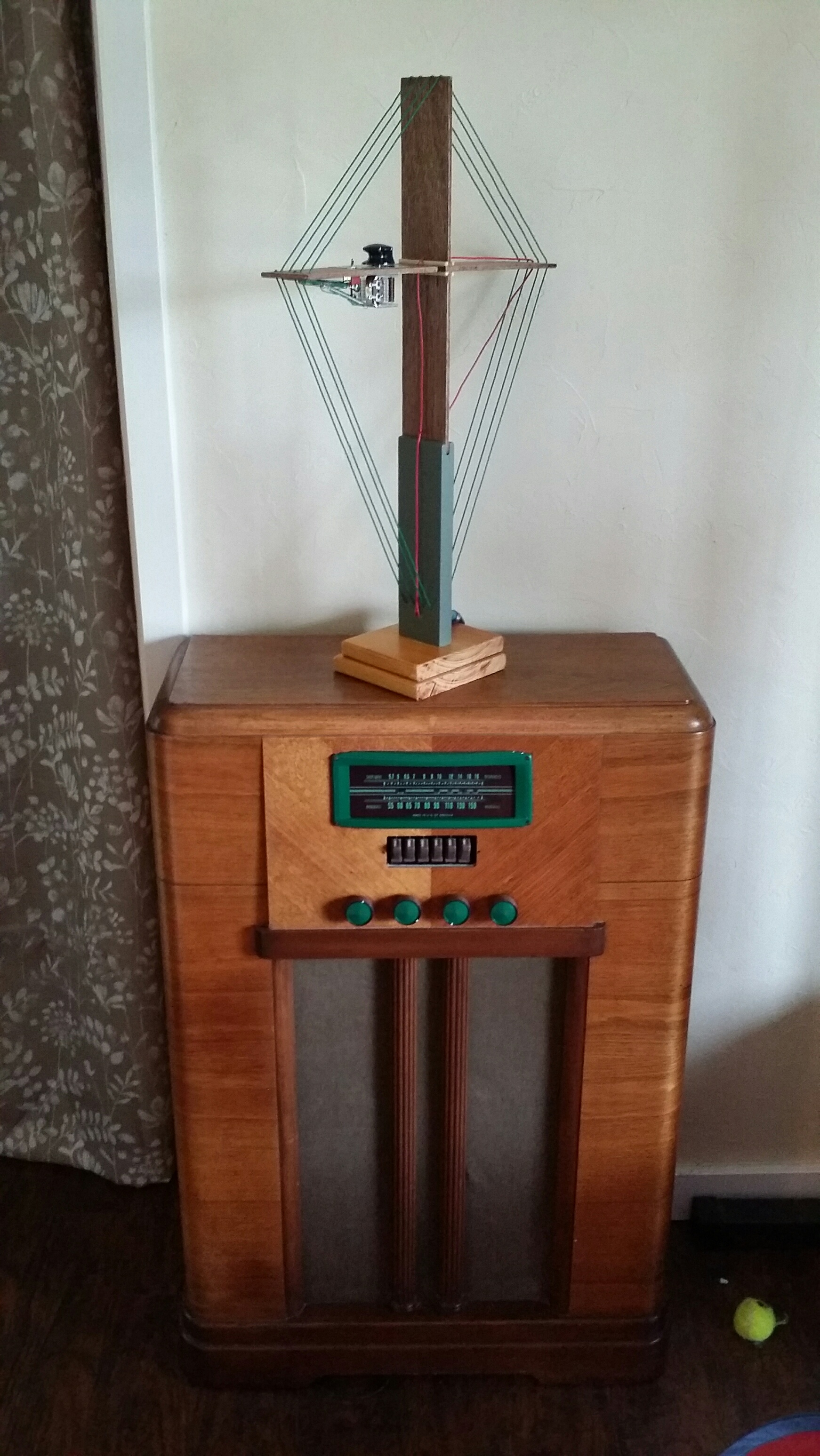
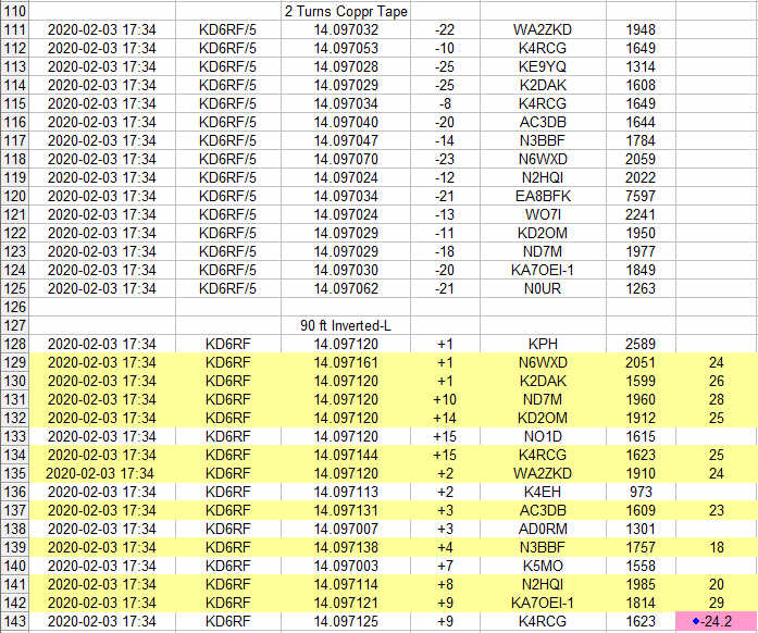
I made a few variations – one to put on top of the old console radio, another using wide copper tape to see if efficiency could be made “usable” for TX with this size loop (no !!).

I was a bit surprised that efficiency for this 2-turn copper tape unit was only about 4 dB better than the wire units above. But still pretty unusable TX efficiency (although fine for RX) on 20 Meters at about 24 dB down from the Inverted-L:
At any rate, this was a useful, fun, and fairly quick project!
copyright Dave KD6RF
5,643 total views, 5 views today