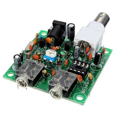
$3 to Quintuple the Output Power of a 40 M Pixie Transceiver

The Pixie is a fun and popular QRP transceiver kit.  However, typical output power on 40 M is only about 300 to 500 milli-Watts – a bit too QRPp at times…

In this article I’ll show cheap and easy ways to pump up the output power to around 1.2 or over 2 Watts, depending upon the power supply type and crystal activity.

Pixie 40 M pic - 2 Continue reading $3 to Quintuple the Output Power of a 40 M Pixie Transceiver

21,845 total views, 6 views today

Please follow and like us:

KD6RF Bio

Consulting RF/microwave engineer specializing in Ultra-WideBand (UWB) circuitry and Antenna design for communications and radar.

  • 3 Year E-Tech ISU 1979
  • Lawrence Livermore National Laboratory Full Scholarship 1988, 1989
  • BSEE UC Berkeley 1990
    GPA 3.98 T.O.C.
  • MSEE 1999
  • 35+ years Lawrence Livermore National Laboratory E-Tech, EE, and Consultant – Hardware, Design, Modeling, Patents, and Applications in UWB Comms, RF OTA Powering, Radar, Antennas
  • Profesional Awards: 2008 R&D100 Secure Cargo UWB Comms  + 2009 Global Security Directorate Award + 2012 Global Security Directorate Gold  + Sensitives

Continue reading KD6RF Bio

3,071 total views, no views today

Please follow and like us:

A Manual PC/Laptop Clock Sync Program for Digital Modes

From the WSJT-X online User’s Manual ===>

SYSTEM REQUIREMENTS
– A means for synchronizing the computer clock to UTC within ±1 second

Using digital communications formats like JT65/9, WSPR, meteor scatter MSK144, or any mode that requires clock synchronization, can be tough without access to network time or a GPS unit.

Continue reading A Manual PC/Laptop Clock Sync Program for Digital Modes

5,779 total views, 1 views today

Please follow and like us:

We Don’t Need No Stinkin’ Sweep Generator …

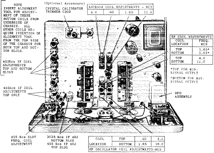
… or any signal generator for that matter in order to align the IF section, including the notorious crystal filter and phasing circuits, of Vintage Receivers like the Hammarlund HQ145 and HQ129X.  It takes about a half hour once you get used to it, perhaps an hour or so the first time.  I’ve aligned my Hammarlunds with this procedure and found the units to be very close to factory spec as measured with standard lab equipment.

A layout diagram, such as the one for the HQ145 below, is useful ===>

hq145toplayout-1
Continue reading We Don’t Need No Stinkin’ Sweep Generator …

8,615 total views, 3 views today

Please follow and like us:

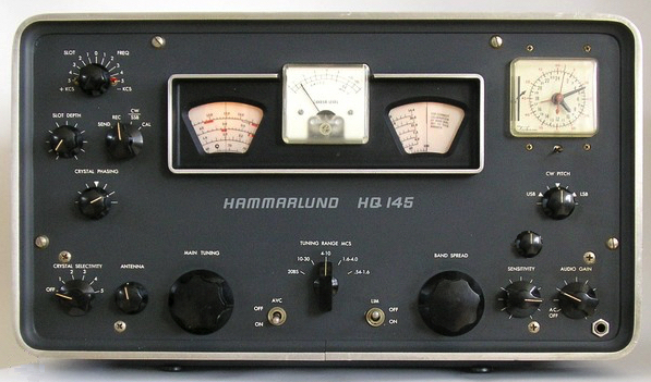
Turning the Hammarlund HQ145 into a Sweet, Sensitive, and Stable Ham Receiver

In this article we will look at a few of the big deficiencies of the Hammarlund HQ145 general coverage shortwave receiver, and put in some fixes.  CW/SSB reception with AGC and S-Meter, stability issues, bandspread, and sensitivity on the high band will be addressed.

Once modified, the HQ145 turns out to be a very nice ham and general coverage receiver all the way up through 10 M.  It’s like my wife: attractive, capable, and a pleasure to be with.  Or, it could be said Sweet, Sensitive, and Stable!

hammarlund-hq145-2

Continue reading Turning the Hammarlund HQ145 into a Sweet, Sensitive, and Stable Ham Receiver

10,335 total views, 7 views today

Please follow and like us:

Why we use a Base Matching Unit (BMU) with End/Base-Fed Verticals and Inverted-Ls

In this article we look at the reduction in feedline loss when we use a BMU to mitigate impedance extremes at the base feedpoint of a Vertical or Inverted-L antenna.  Naturally, these antennas are worked against a proper counterpoise radial system for decent efficiency, especially on the low bands.

We look at the cases of a 42 ft antenna, and use an average of the measured and modeled feedpoint impedance to calculate feedline losses* for 50 ft of RG8x and for 100 ft LMR400.

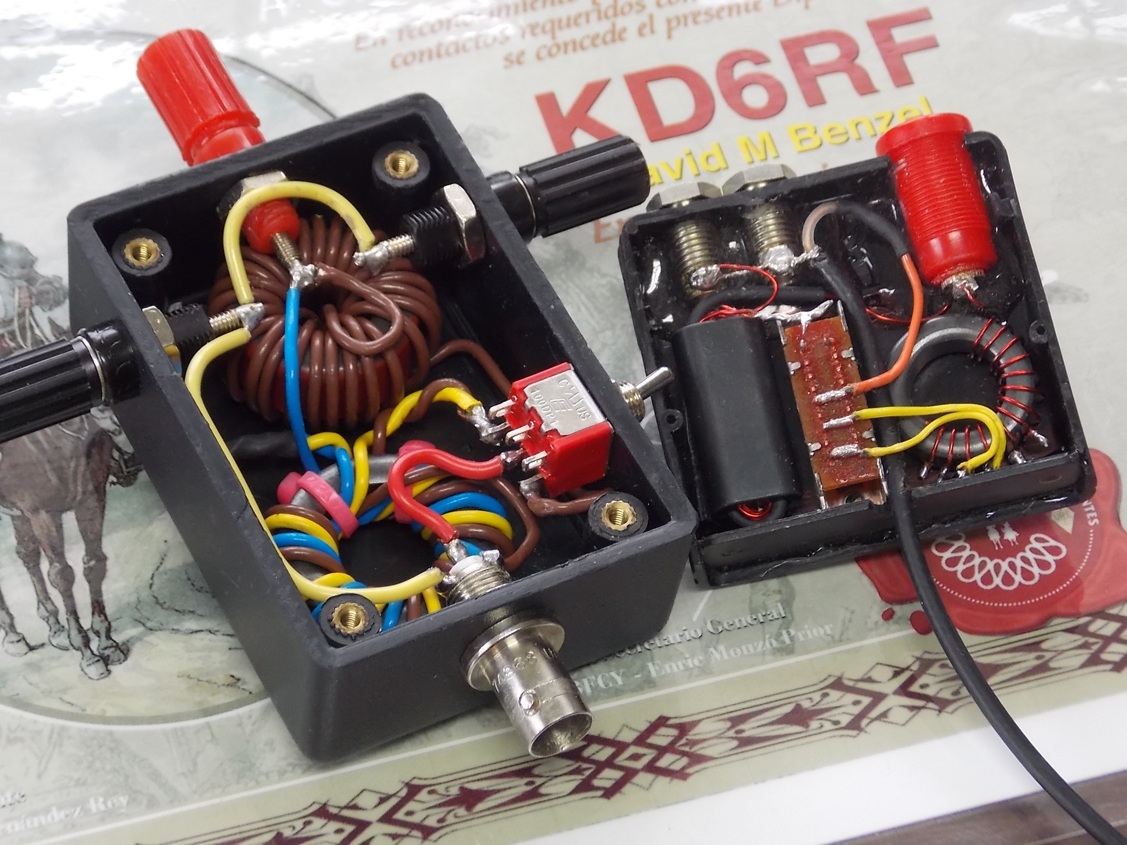
BMUs Bottom View Portable QRP and Med Power

The BMU referred to here is:

A 9:1 UNUN for the mid and high bands
A Loading Coil, switched in instead of the UNUN, for the low bands

Continue reading Why we use a Base Matching Unit (BMU) with End/Base-Fed Verticals and Inverted-Ls

4,544 total views, 3 views today

Please follow and like us:

End/Base-Fed Inverted-L, 90 ft and 45 ft versions, Feedpoint Impedance and SWR

Below are presented the results of actual measurements as well as EZNec modeling of both a 90 ft long End/Base-Fed Inverted-L 45 ft high and 45 ft across, as well as a 45 ft long Inverted-L 23 ft high and 22 ft across. Measurements of both were taken with a combination of a RigExpert AA-1400 and an HP8510 Vector Network Analyzer.

The 90 ft antenna is suspended by a pair of tall LobLollies, and is driven against a counterpoise system consisting of 14 surface ground radials and a low chain link fence.

loblolly-antenna

Continue reading End/Base-Fed Inverted-L, 90 ft and 45 ft versions, Feedpoint Impedance and SWR

5,212 total views, 7 views today

Please follow and like us:

Z of EFHW vs. “Counterpoise” Length

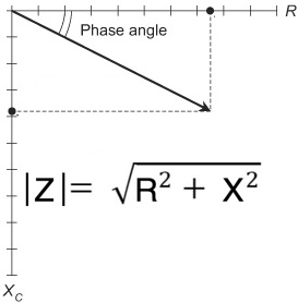
We look at the magnitude of the impedance of an EFHW “antenna” for short counterpoise lengths.

Thanks to Jon AF7TS for the suggestion and discussions that led to this article.

In engineering we sometimes can not directly calculate a value, often when a “divide-by-zero” shows up, as when we try to calculate an impedance wiith a zero length element.  However we can usually still tell what that value will be by sneaking up next to it and determining what it asymptotically approaches.

sqrt-sum-of-squares-4 Continue reading Z of EFHW vs. “Counterpoise” Length

10,949 total views, 4 views today

Please follow and like us:

Current Flow Example for an “End-Fed” Antenna with a Loss-Less Choke

A simple transmitter, transmission line, and an “End-Fed” antenna WITHOUT a formal “Counterpoise” – We add a loss-less choke at the feedpoint, tune out it’s inductance with a capacitor, and see why common-mode current on the coax shield is the SAME as without the choke.

From Part 1 and Part 2 of the “Current Flow Fundamentals for an “End-Fed” articles, we saw that common-mode current must always flow on the coax shield when we don’t use a formal counterpoise.  And that the value of current on the “counterpoise” is identical to that on the “radiator” at the feedpoint.

In Part 3 we saw that it doesn’t matter what loss-less device(s) we put at the feedpoint – when we re-adjust our transmitter or tuner the SAME current flows common-mode on the shield as before.
choked___transformer_to_-efhw-2-1

Continue reading Current Flow Example for an “End-Fed” Antenna with a Loss-Less Choke

5,391 total views, no views today

Please follow and like us: