Part 2 – A 40 Meter EFHW with a “Radiator” wire and various length “Coax-as-Counterpoise” wires is analyzed – We will see that the common-mode current is almost always LARGER on the coax shield some distance away from the feedpoint, which is why the “counterpoise” radiates and is called “the other half of the antenna”.
It is sometimes said that common mode current flow on the coax shield of an “End-Fed” antenna system is everywhere low, simply because the feedpoint current is relatively low. This is claimed even for systems with no “counterpoise”. In this article we will see that this is not true.
“…charge conservation is the principle that electric charge can neither be created nor destroyed.”*
As shown in Part 1, from this perfectly reasonable principle we now know that there are NO 1-Terminal RF power sources!
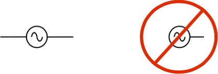 2 Terminals – YES! 1 Terminal – NO!
And just as true (graphic from Steve AA5TB’s website) No 1-Terminal RF Sources or Antennas:
 Now that we know that our transmitter or RF source as well as our antenna must have 2-Terminals**, we note that we can put the words “Radiator” and “Counterpoise” in quotes. This is because basic antenna principles, EZNec modeling software, and current meters, don’t know or care what each wire is called. Current flows on both wires, and therefore both wire radiate. To what extent we will explore below.
We can now easily analyze the amounts of current flowing on both wires, the left and right wires of the antenna. We will look both at the feedpoint, and at the current maxima for our typical ham “end-fed” installation.
 For a 67 ft EFHW “radiator” vs. various length “counterpoise” we get the following currents measured at the feedpoint left-hand “radiator” and right-hand “counterpoise” wires. The coax-as-counterpoise is grounded (or is capacitively coupled to ground):
FOR CURRENTS MEASURED AT THE FEEDPOINT:
(note that “feed point L” and “feed point R” mean Left and Right wires)
| CP Length ft | I feed point L | I feed point R | dB |
| 67 | 1.0 | 1.0 | 0.0 |
| 62 | 1.0 | 1.0 | 0.0 |
| 57 | 1.0 | 1.0 | 0.0 |
| 47 | 1.0 | 1.0 | 0.0 |
| 37 | 1.0 | 1.0 | 0.0 |
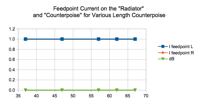 Now that we know all about charge conservation and KCL, it shouldn’t be surprising that the current flowing in both wires at the feed point is the SAME.
So, if the current is “small” at the feedpoint, is it small everywhere? – NO!!!
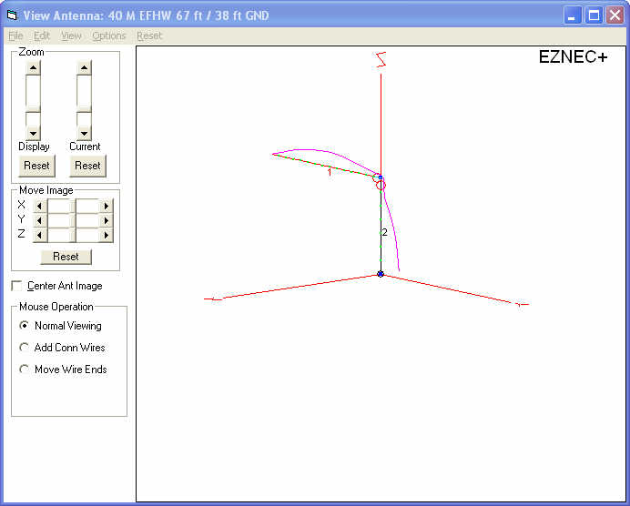
FOR CURRENTS MEASURED AT THE MAXIMA – GROUNDED “COUNTERPOISE” CASE:
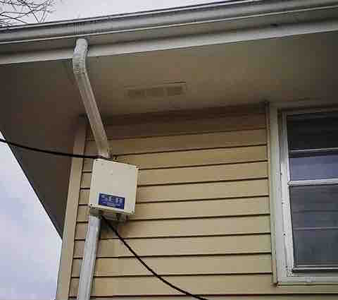
This case is usually a realistic representation of the typical ham installation – where the shield “counterpoise” is brought downward and is tied to ground either by design , or through the house/ shack wiring.
As above, we vary the “counterpoise” (the Right hand wire) length to values seen in typical installations, and plot and measure the value of current at the maximas ===>
 Numerically (note that “I max L” and “I max R” mean Left and Right wires, the Right wire being the Grounded “Counterpoise”):
| CP Length ft | I max L | I max R | dB |
| 38 | 4.1 | 6.3 | 3.7 |
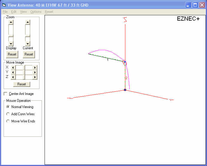
| 33 | 6.0 | 4.1 | -3.3 |
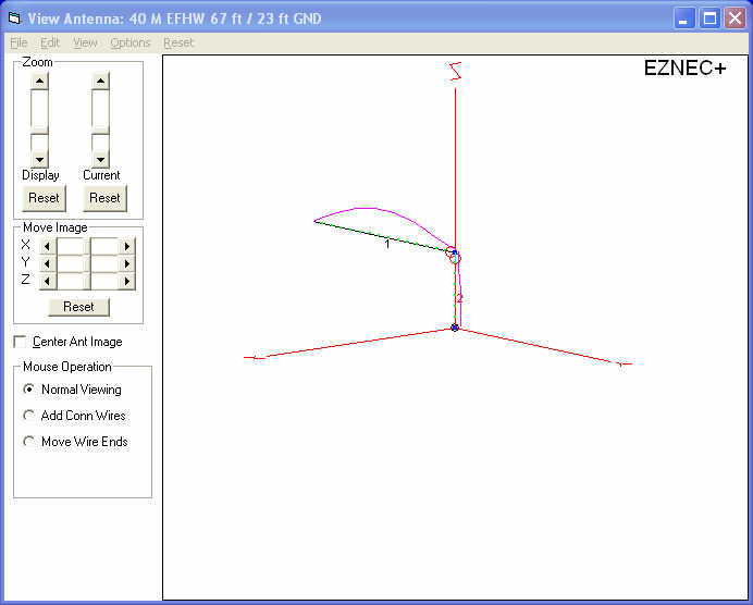
| 23 | 7.1 | 2.0 | -11.0 |
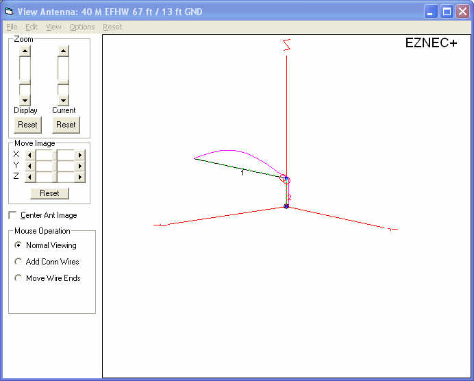
| 13 | 7.0 | 1.3 | -14.6 |
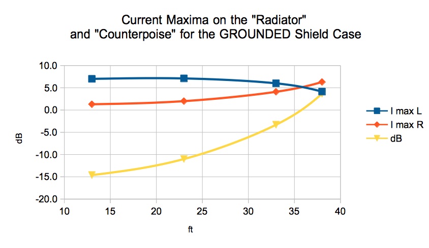 Clearly for these cases, the current flowing on the “counterpoise” wire at the current maxima is ALWAYS larger than that flowing at the feedpoint, can be GREATER than that on the “radiator” itself, is always quite significant, and is a function of length.
The single rarely achievable “best case” exception is a grounded 1/2 wavelength “counterpoise”, where the current at the grounded end is equal to that at the feedpoint. We say “rarely achievable”, since most installations will not have the feedpoint a full 1/2 wavelength in the air, but rather is at lower heights, and is directly connected or capacitively coupled to ground at some length shorter than 1/2wavelength.
Naturally, current flowing into Lossy Ground means some loss in efficiency.
In Part 3 we will attach some impedance matching devices as well as a choke at out feedpoint, and see what happens to current flow in an “end-fed” antenna system with no formal counterpoise.
________________________________TAKE AWAYS
- The current at the feedpoint is always EQUAL on both wires.
- The current on the GROUNDED “counterpoise” varies along its length just like the “radiator”, and is (with one exception) LARGER than that at the feedpoint, or even than on the “radiator” itself.
- The “counterpoise”, whether a formal counterpoise wire or the coax shield, RADIATES because it has current flow just like the “radiator”.
Dave Benzel – KD6RF – 2016 Dec 25
* With the exception of some nuclear level processes where charge is conserved.
** If this seems mysterious, please first read “Tutorial: Current Flow Fundamentals for an “End-Fed” Antenna, Part 1“
8,046 total views, 1 views today