An interesting pro-bono project: design a conformal antenna for a university class-project rocket’s data link.


The existing antenna, simply a half-wave dipole taped to the metallic rocket body obviously didn’t work.
One natural design is a pair of standard probe fed patches of around 20 cm. Duroid substrate material is nice and flexible. A pair of patches (in this case microstrip fed) in phase also wrapped circumferentially. The 4 active radiating gap regions could very well mitigate/eliminate any rotational dropouts.
Sonnet Lite was used to model the antenna – https://www.sonnetsoftware.com/products/lite/
It is showing 5 or 6 MHz BW for 2mm substrate, but the eval lite version won’t show far field results which, I imagine, would allow us to directly see the efficiency.
RE link margin: rough conservative calcs (Friis free space) show we need about -10 dBi antenna gain on the TX end to get us a 25 dB SNR at the receiver (2W TX, 15 dBi RX ant, 5 dB noise fig, 150 kM, 100 kHZ bandwidth).
So, if the wrap around 2 mm thick substrate single patch, or dual patch, is mechanically acceptable, and our center freq vs temp is ok, then this would be a solution to the problem if we can be -10 dBi or better (obly around 5 or 10 % efficient).
Some results from Sonnet Lite modeling an approx 20 cM X 15 cM standard probe fed rectangular patch, 2mm thick RT6002 substrate
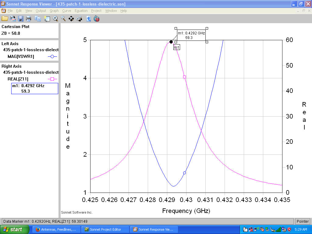
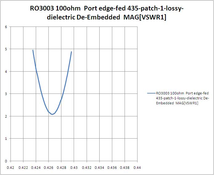
Lossy case, er =1.2e-3, SWR and Re(Zin)
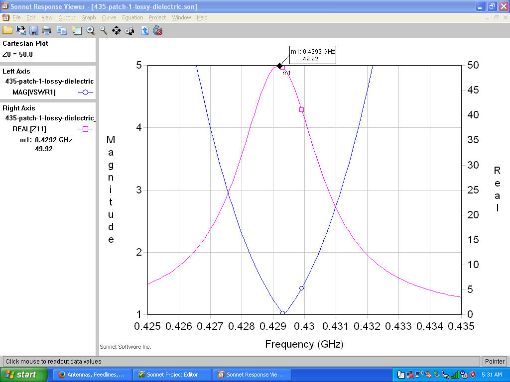
SWR BANDWIDTH—-> 2:1 SWR BW from Sonnet plots is approx 2 MHz.
EFFICIENCY ——–> From “Millineter-Wave Mictrostrip and Printed Circuit Antennas”, Bhartia, Rao, and Tomar, 1991, p 105, eff is the ratio of lossless to lossy Zin at resonance. From the Sonnet plots, eff = 49.92/59.2 = 0.84. Not bad.
TEMPERATURE EFFECTS —-> From RT6002 data sheet, dielectric constant varies at 12 ppm / degree C. @T0, er=2.9. @T0+200C, er=2.94696. fres@T0=429.3MHz. fres@T0+200C=428.8MHz. Delta f over 200C temp range = 500kHz. Lookin’ good, assuming we have a few hundred C temperature variation or less.
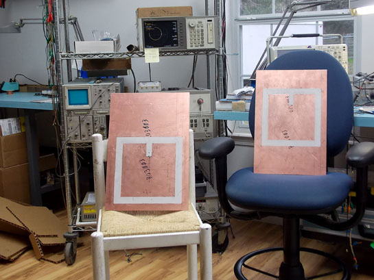
Here is the nice equal current distribution on the dual patch setup. I think this is the one we want – note that the dimensions work out nicely such that the 4 radiating edges are close to equally distributed around the rocket body when wrapped around it – there is always a radiating gap pointing at the reciever, so this should greatly reduce signal fade as a function of rocket body rotation—->
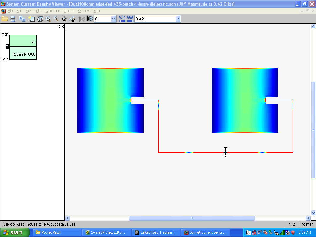
The matching is set up so that the antennas have a 100 ohm feedpoint, and are feed with 1 mm wide 100 ohm microstrip. They are in parallel at the via point, where the center conductor of the 50 ohm coax is fed through –
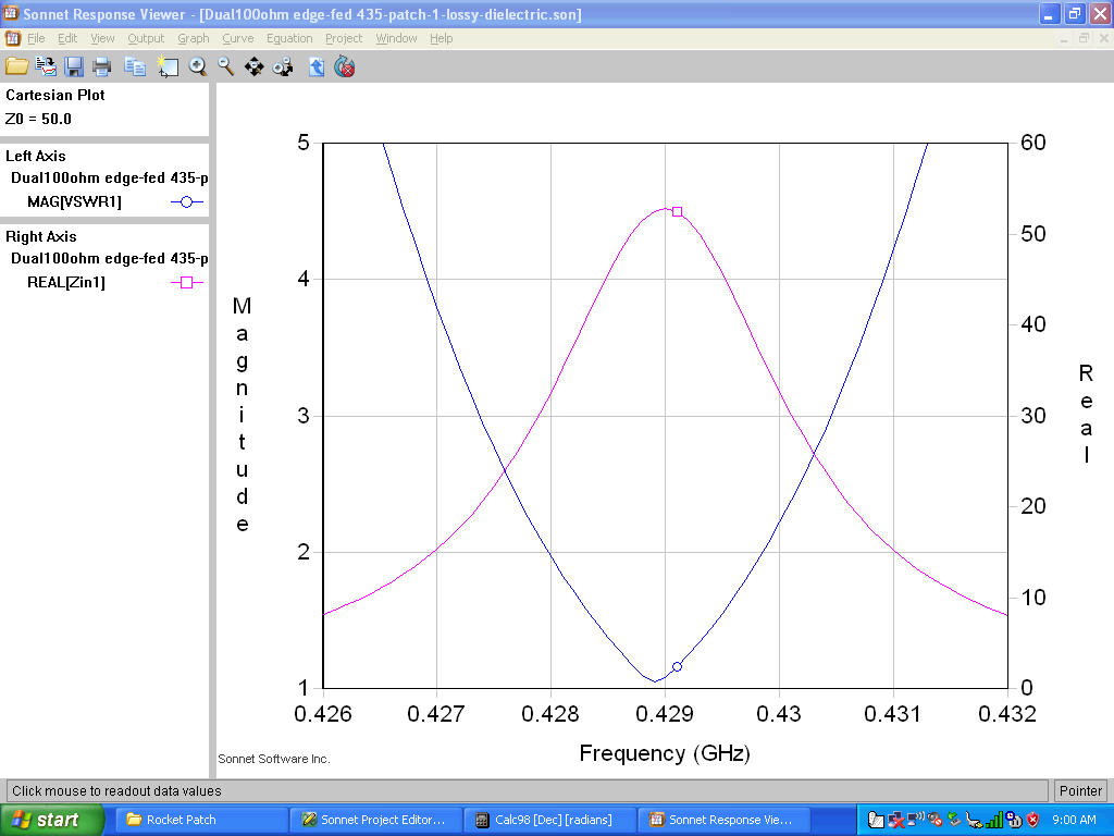
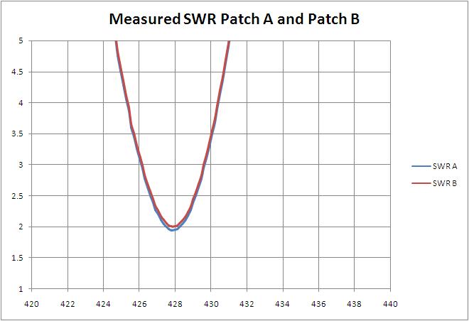
Still around 2 MHz 2:1 SWR bandwidth – a bit narrower than we would like, but use-able.
Sonnet predicted the resonant frequency as close as can be, given that the patches were hand carved!. Oddly enough, Sonnet seems to have gotten the feedpoint Z off – I measured 150 ohms instead of the 100 ohms desired. No worries, it was easy enough to move the feedpoint back the 4 or 5 millimeters to get 100 ohms.
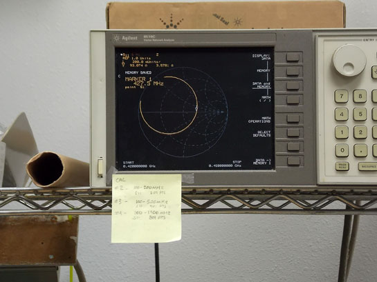
Measured BW was about 3.8 MHz, Sonnet predicted about 3.4 MHz (at the 3:1 points), so we are pretty close there. Both patches (once one of them was tweaked) were within a few ohms of 100 at the feedpoint.
If these will be produced, one may want to add some tiny tuning tabs to the pattern, or just solder on some little tabs as I did here in order to get the pair virtually identical.
So, it turns out that it’s not easy to accurately cut .06 wide copper tape. Doh! But it was close enough for proof of concept in driving the pair of patches in phase as per the Sonnet layout above. The SWR was 1.2, instead of flat, and resonant freq changed a few hundred kHz, but close enough for the prototype.

It also turns out that copper tape isn’t robust enough to survive the forming of cylinder to wrap around rocket body. Neither were my little copper tabs. So, I took off the tabs, disconnected the 100 ohm copper tape transmission lines, and re-installed the SMA probe feeds.
If it is decided to produce and use this antenna, I have no doubt that a normal production unit would be just fine – perhaps it would be rolled similar to how sheet metal is formed and curved. Of course, one would want to make sure, as the 100 ohm interconnect lines are a bit on the small side.
Anyway, I hand bent the individual units, wrapped, bungeed and clamped them around the only thing I had that was close in diameter (a 12″ diam bucket), plumbed in a combiner, hooked it all up to the hand-held and ran azumithal patterns compared to the reference dipole (seen on the table next to the scope/spect analyzer).
Reference dipole is of the Pawsey Stub type, RX antenna is a standard EMC log periodic, Spect Analyzer is part of my new favorite scope, the Tektronix MDO3104 (also 4 chan 1 GHz real time scope that takes the place of my previous favorite: the old Tek 7104 image intensifier 1 GHz scope).
Efficiency turned out to be decent for such a thin antenna at about -3 dBi at the peaks. Valleys were down 7 dB.
Many thanks to the folks at Rogers Corporation for donating several pieces of low loss low temperature coefficient RT Duroid circuit board material to the university project. http://www.rogerscorp.com/acs/producttypes/6/RT-duroid-Laminates.aspx
Feel free to use this design information for non-commercial purposes.
Dave Benzel – KD6RF – 2016 Oct 23
4,667 total views, 1 views today