Part 1 – A simple transmitter, transmission line, and an “End-Fed” antenna WITHOUT a formal “Counterpoise” – We will see why common-mode current must ALWAYS flow on the coax shield.
End-Fed Antennas have been around since the good ‘ol days and were once most popular. Yet for some reason, much discord still exists regarding the “counterpoise” – what its behavior is, or if one is even needed. Not all that surprising since the term “counterpoise” doesn’t seem to have a firm definition. Hopefully, we can figure out what’s going on despite the semantics, and deal only with easy to understand basic principles.
Principles like this from basic physics:
“…charge conservation is the principle that electric charge can neither be created nor destroyed.”*
From this perfectly reasonable principle we get Kirchoff’s Current Law (KCL) which tells us that the current flowing OUT of a source node on one terminal must also flow IN on the source node’s other terminal – meaning that there are NO 1-Terminal RF Power Sources any more than there are 1-Terminal alternators!
 Schematically, this means:
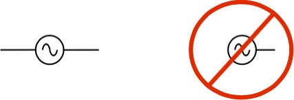 2-Terminal RF Sources – YES! 1-Terminal RF Source – NO!
And as illustrated by Steve AA5TB’s graphic from the good work on his website:
… naturally there can be NO 1-Terminal RF Sources or Antennas!
OUR 2-TERMINAL TRANSMITTER AND TRANSMISSION LINE
Just like ten’s of thousands of others out there, here’s our 2-Terminal transmitter with it’s internal tuner, and coax transmission line. For convenience, we adjust our RF Source Transmitter so that 0.522 Amps is measured flowing on the center conductor of our coax – this value represents about 1 kW into a bit more than 3.6K ohm impedance assumed for this example “end-fed” antenna. And assume for this example that our loss-less coax transmission line is 1/2 wavelength long – meaning that we have 0.522 Amps flowing at the far end on the center conductor as well ===>
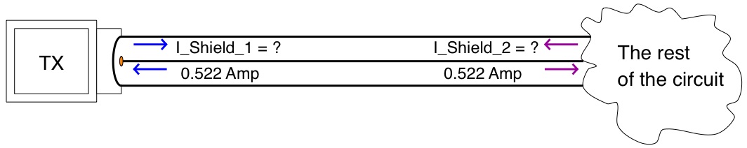
With this 0.522 Amps flowing on the center conductor of our coax:
Q1 – How much total current is flowing on the inside of the shield conductor at I_Shield_1 ?
——- and ——-
Q2 – How much total current is flowing on the inside of the shield conductor at I_Shield_2 ?
(Hint —> the answers are real easy and don’t require a calculator!… )
)
.
.
Let’s start filling in the answers for the currents. We now know that:
– There are NO 1-Terminal RF Sources
– And that charge conservation and KCL tell us that the same amount of current flowing IN to a source node must also flow OUT of the source node……..Therefore:
Q1 Answer —> 0.522 Amps flowing on one terminal of the RF Source (the center conductor) ALSO means that I_Shield_1 = 0.522 Amps flowing on the other terminal of our RF Source (the inside surface of the coax shield).
——– and ——–
Q2 Answer —> 0.522 Amps flowing on the center conductor at the far end ALSO means that I_Shield_2 = 0.522 Amps flowing on the inside of the coax shield at the far end, as shown below ===>
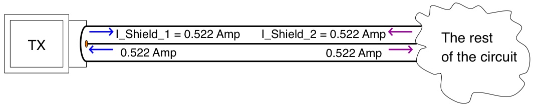
WE CONNECT OUR TX AND COAX TO AN “ANTENNA”
Now we add “The rest of the circuit”. Guess what? – It’s an “End-Fed” antenna!
And we now ask a few more Questions – the first is What is I_feedpoint equal to? ===>

And the Answer – Of course it’s equal to the current on the center conductor and is I_feedpoint = 0.522 Amps, for exactly the same reasons discussed above …… and as illustrated below ===>

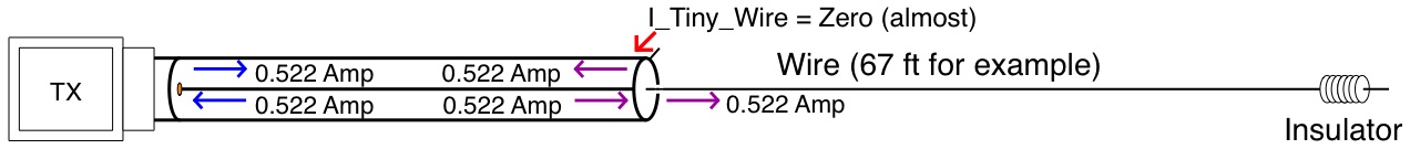
Note that at the feedpoint location naturally we have 0.522 Amps flowing on the inner surface of the shield as well, also for exactly the same reasons discussed above …….
Question – Where do all those electrons come from at the end of the coax in order to supply 0.522 Amps to the inner surface of the shield? (keep in mind the physics factoid “electric charge can neither be created nor destroyed.”)
Note that our Tiny Little Wire at the end of the coax is sooooo small, compared to a wavelength, that it’s almost not there. IOW ===>
So where does our 0.522 Amps come from? Answer – The 0.522 Amps MUST be supplied by a current flow on the outside of the coax shield. This is illustrated below ===>
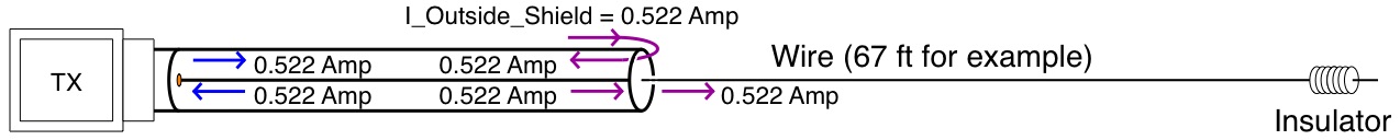
We therefore have 0.522 Amps of Common Mode Current flowing on the outer surface of the coax shield at the feedpoint.
In Part 2, we will look at how the current magnitude varies along the length of the “radiator” and “counterpoise”.
There are a number of other well grounded (so to speak) Hams and Professionals that also address this issue from slightly different perspectives. Owen, ex VK1OD, has a nicely written article on current flow in/on a coaxial transmission line. If you are interested in more detail ====>
http://owenduffy.net/blog/?p=428
 Thanks to the good folks on QRZ.com for constructive suggestions, and to Dave ther well reasoned and written articles on this and similar subject matter by Tom w8JI, Steve AA5TB, and Palomar Engineers ===>
http://www.w8ji.com/end-fed_1_2_wave_matching_system_end feed.htm
http://www.w8ji.com/end-fed_vertical_j-pole_and_horizontal_zepp.htm
http://www.aa5tb.com/efha.html
http://palomar-engineers.com/tech-support/tech-topics/end-fed-antennas
________________________________TAKE AWAYS
- An RF Source and an “End-Fed” Antenna ALWAYS have two terminals. There may be others paralleled (which still reduces to only 2 by KCL), but there can never be only 1.
- The current magnitude at the feedpoint is EQUAL on both wires.
- Without any formal “counterpoise” ALL of the current on the inner shield flows also on the outside of the shield – the is called Common Mode Current.
Dave Benzel- KD6RF – 2016 Dec 28
* With the exception of some nuclear level processes where charge is conserved.
17,415 total views, 3 views today