A simple transmitter, transmission line, and an “End-Fed” antenna WITHOUT a formal “Counterpoise” – We add a loss-less choke at the feedpoint, tune out it’s inductance with a capacitor, and see why common-mode current on the coax shield is the SAME as without the choke.
From Part 1 and Part 2 of the “Current Flow Fundamentals for an “End-Fed” articles, we saw that common-mode current must always flow on the coax shield when we don’t use a formal counterpoise. And that the value of current on the “counterpoise” is identical to that on the “radiator” at the feedpoint.
In Part 3 we saw that it doesn’t matter what loss-less device(s) we put at the feedpoint – when we re-adjust our transmitter or tuner the SAME current flows common-mode on the shield as before.
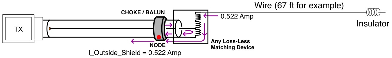
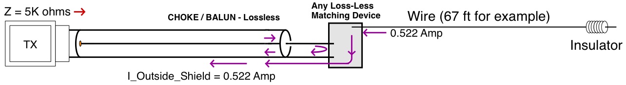
We start with the same system as in Part 3, but also include the value of the feedpoint impedance 1/2 wavelength away at the TX / Tuner ===>
ADD A LOSSLESS CHOKE AND RE-TUNE:
Now we add a Loss-Less Choke of 4K ohms inductive reactance at the feedpoint. In our tuner at the transmitter side 1/2 wavelength away, we tune out the 4K ohm inductive reactance with a 4K ohm capacitive reactance ===>
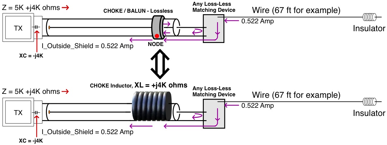
The Loss-Less Choke is pictorially shown above equivalently as a coil to make clearer that it is simply a common mode inductor.
MOVE THE CAPACITOR TO THE FEEDPOINT AND RETUNE:
Since our example transmission line is 1/2 wavelength long, we can move the 4K ohm capacitve reactance to the feedpoint and see that it is now simply a resonant series tuned circuit with XL ===>
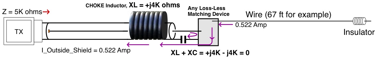
![]() Since XC cancels XL at our resonant frequency, we can remove the choke inductor and the capacitor from our diagram and replace with a wire – We see that this is exactly the original Choke-less circuit ===>
Since XC cancels XL at our resonant frequency, we can remove the choke inductor and the capacitor from our diagram and replace with a wire – We see that this is exactly the original Choke-less circuit ===>
…and that the currents at the feedpoint, and common-mode on the coax shield, is also exactly the same in all above cases as we tune and re-tune our matching network to put out the same amount of power into the new load impedances.
For the case of a lossy choke, the principle remains the same, but both “radiator” and “counterpoise” feedpoint currents are identically reduced to account for power lost heating the choke.
________________________________TAKE AWAYS
- Without a formal counterpoise ALL of the current that flows on the “antenna” wire at the feedpoint also flows on the coax shield as Common-Mode Current.
- Without a formal counterpoise, the current magnitude at the feedpoint is IDENTICAL with or without a (loss-less) choke at the feedpoint, once matching is re-adjusted to put out the same amount of power into the new load impedance.
- Since current ALWAYS flows on the shield in a system without a formal counterpoise, the shield radiates, and is part of the antenna. The extent to which it radiates varies as shown in Part 2 of this series.
Dave Benzel- KD6RF – 2017 Jan 1
6,231 total views, 3 views today