… or any signal generator for that matter in order to align the IF section, including the notorious crystal filter and phasing circuits, of Vintage Receivers like the Hammarlund HQ145 and HQ129X. It takes about a half hour once you get used to it, perhaps an hour or so the first time. I’ve aligned my Hammarlunds with this procedure and found the units to be very close to factory spec as measured with standard lab equipment.
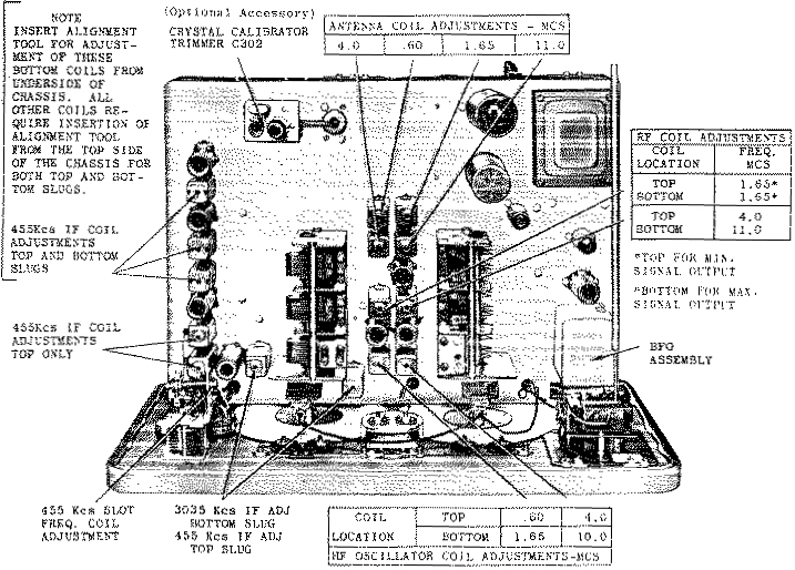
A layout diagram, such as the one for the HQ145 below, is useful ===>
Having acquired some gorgeous Hammarlunds a few years ago, I found that they mostly worked. But the filter/phasing alignment was was wayyyy off, perhaps due to aging, or judging by the marks on the alignment screws and cans, due to a previous owner giving up on the alignment of the filter section.
 So, here is the procedure I came up with for aligning the HQ145 and HQ129X. The steps are:
1) and 2) – find and tune a station onto the IF crystal filter frequency
3) – align the rest of the IF sections to the frequency of our crystal filter
4) and 5) – align the crystal filter/phasing section
6) – verify filter center freq and passbands and perform slight re-tweek if necessary.
1) Tune in a low strength signal – AM radio is probably best. We want a signal that is weak so that we hear the white noise hiss along with the signal.
2) Turn selectivity control to max. Turn phasing control straight up (plates of phasing cap half way in both stators). No matter how badly the IF and filter circuits are misaligned, you will still be able to find the very sharp crystal filter frequency. Carefully tune receiver to show max reading on S-meter.
— At this point we hear a very muffled AM radio station and have tuned the receiver such that we have nailed down the crystal frequency that the rest of the IF sections and filter will be aligned to. It turned out to be 455.8 KHz in my case.
3) Turn selectivity control off. Without changing the receiver’s frequency, align all IF transformers and coils (excluding the crystal filter units) as we normally would – peak them for max S-meter reading. Some peaks are fairly broad – try to center them up.
— Old timers will probably remember doing this without an S-meter by listening to the signal and tuning the transformers/coils for minimum high frequency sound content. When you have swooshed in the sound of the AM station in this way, you know that all transformers/coils are well centered on the IF.
4) Turn selectivity control to some low setting – 1 or 2 works well. Again, without changing the receiver’s frequency, tune the slug of the second crystal filter section can (second can from front panel for the HQ145) or the upper screw (for the HQ129) so that you hear maximum high frequency content. It should sound only slightly muffled, with no ringy-ness.
5) Peak up the slug of the first crystal filter section can (closest can to front panel for the HQ145) or the lower screw (for the HQ129) for max S-meter reading.
6) I noted some interaction between the last two alignments, and to a lesser extent the IF transformers/coils. Switch back to max selectivity and make sure our AM station is tuned to max S-meter reading. Switch up and down the selectivity switch settings and you should see just what is described in Hammarlund’s manuals – you should see that the S-meter shows peak reading at exactly the same setting of the tuning dial on our AM station. Re-tweek the slug of the second crystal filter section can (for the HQ145) or the upper screw (for the HQ129) if you see any difference in the position of the tuning dial for max S-meter reading among the selectivity settings. Careful, only very slight movements of the slug or screw at this point. A bit of re-tweeking of the IF transformers/coils will give us a nice symmetrical passband for all settings of the selectivity control, including “Off”.
That’s it.
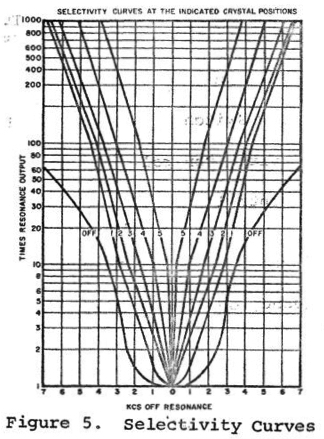
Tuning in to a stronger AM station, and tuning around while observing the S-meter, I found that the published Hammarlund curves were quite close for the two receivers I aligned. Listening to SSB signals, the phasing control now works nicely along the lines of a modern RIT receiver where you can greatly attenuate an interfering signal above or below the desired frequency.
I find that selectivity settings of 1, 2, or 3 are nice for SSB, settings 4 and 5 are great for CW.
Hopefully this helps those who don’t have access to signal generators or sweep generators.
This is an update of the original post on qrz.com ===> https://forums.qrz.com/index.php?threads/we-dont-need-no-stinkin-sweep-generator.280341/
Dave Benzel – KD6RF – 2011-Jan-11
13,487 total views, 2 views today
I have both these rigs and will run this procedure on them! We have a local station that drops to 500w at night. It may work. Others are too strong. Distant stations suffer QSB.
73 DE JIM K6FWT
GL – hope this helps!
Hi!
Thanks for the site and info on the HQ-145. I have a question for you, if you have time.
With reference to the Alignment Page in the manual, in the “RF Coil Adjustments” box, you will note some asterisks. My problem is with the one which states “Tune the top for minimum signal output”.
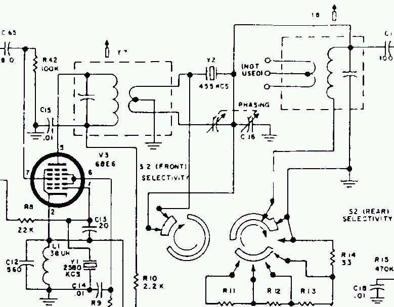
Now it’s possible to tune 1.65Mc on Band 1, and to 1.65Mc on Band 2 as well, which is the point of these adjustments. However, “Tune top for minimum signal”? Really? Looking at the circuit, it appears that isn’t even possible! The coil is L4. The top slug should be adjusted to peak the band 1 1.65Mc signal with the Antenna Trimmer cap near minimum (top of the band). Hammarlund had years to discover and correct this with various editions of the receiver (145X, 145A) but they didn’t. Have I missed something? Thanks.