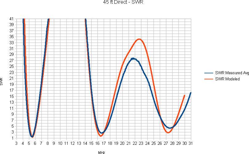
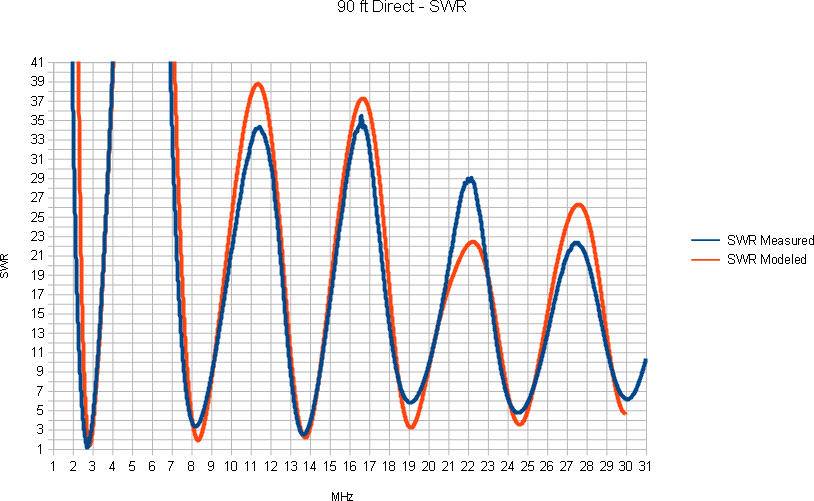
Below are presented the results of actual measurements as well as EZNec modeling of both a 90 ft long End/Base-Fed Inverted-L 45 ft high and 45 ft across, as well as a 45 ft long Inverted-L 23 ft high and 22 ft across. Measurements of both were taken with a combination of a RigExpert AA-1400 and an HP8510 Vector Network Analyzer.
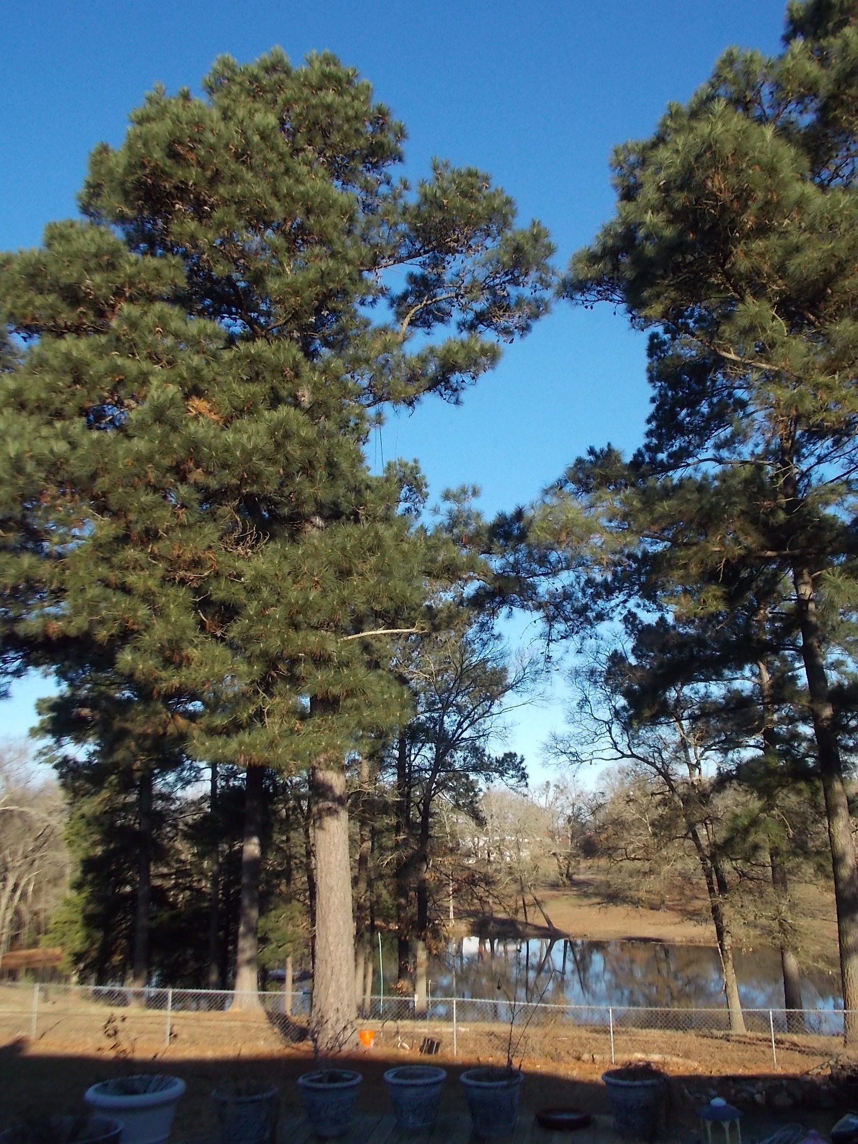
The 90 ft antenna is suspended by a pair of tall LobLollies, and is driven against a counterpoise system consisting of 14 surface ground radials and a low chain link fence.
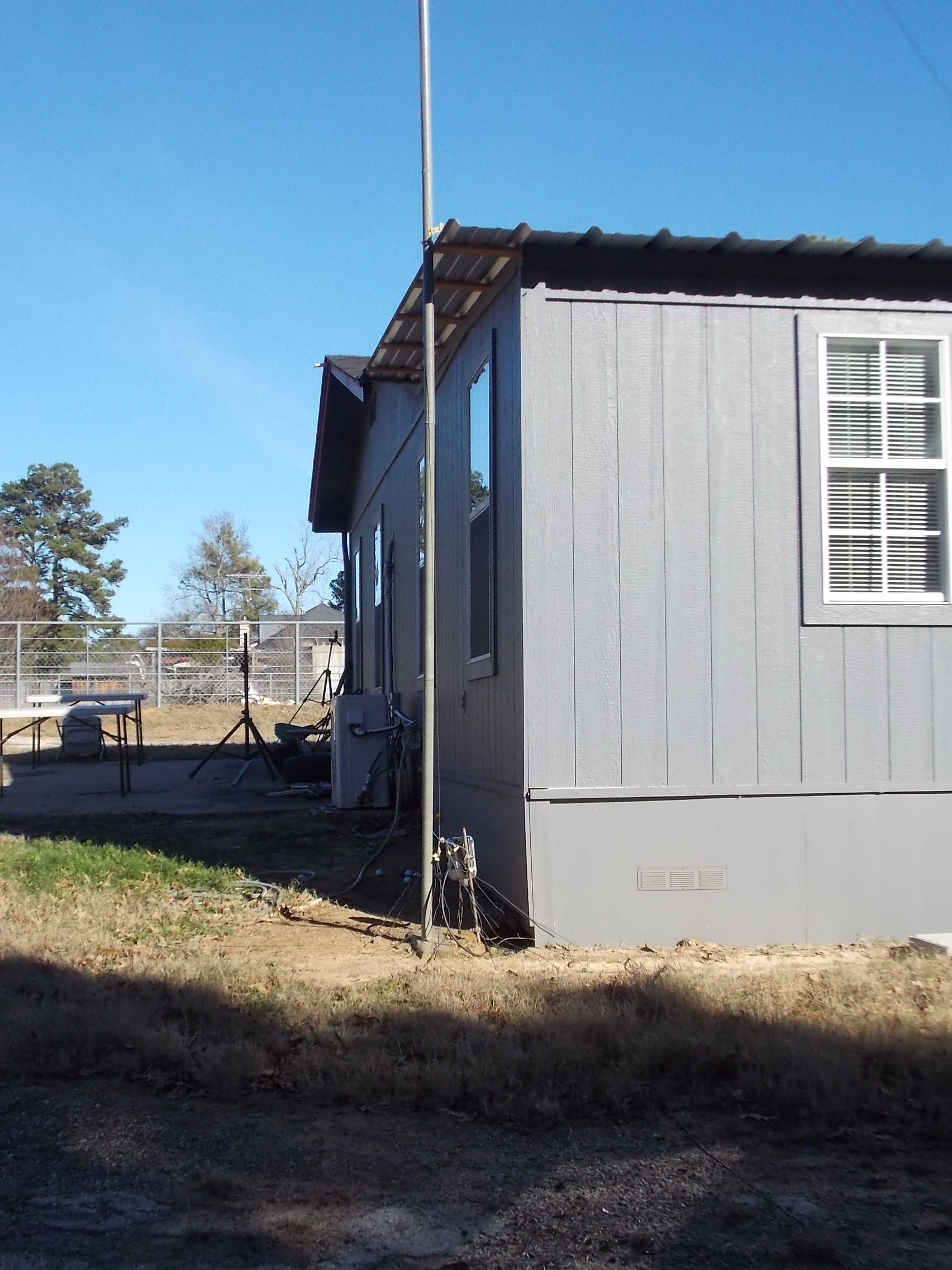
The 45 ft antenna is supported by guyed mil tent poles and suspended to another LobLolly. This unit is driven against 16 surface ground radials.
For modeling purposes, a multi-connection distributed grounded counterpoise is used. This empirical structure provides a reasonable broadband counterpoise over the frequency range of interest.
MEASURED AND MODELED SWR
We see good agreement between modeled SWR and measured SWR for both the 90 ft antenna and the 45 ft antenna ===>
Dave Benzel – KD6RF – 2017 Jan 4
6,255 total views, 1 views today
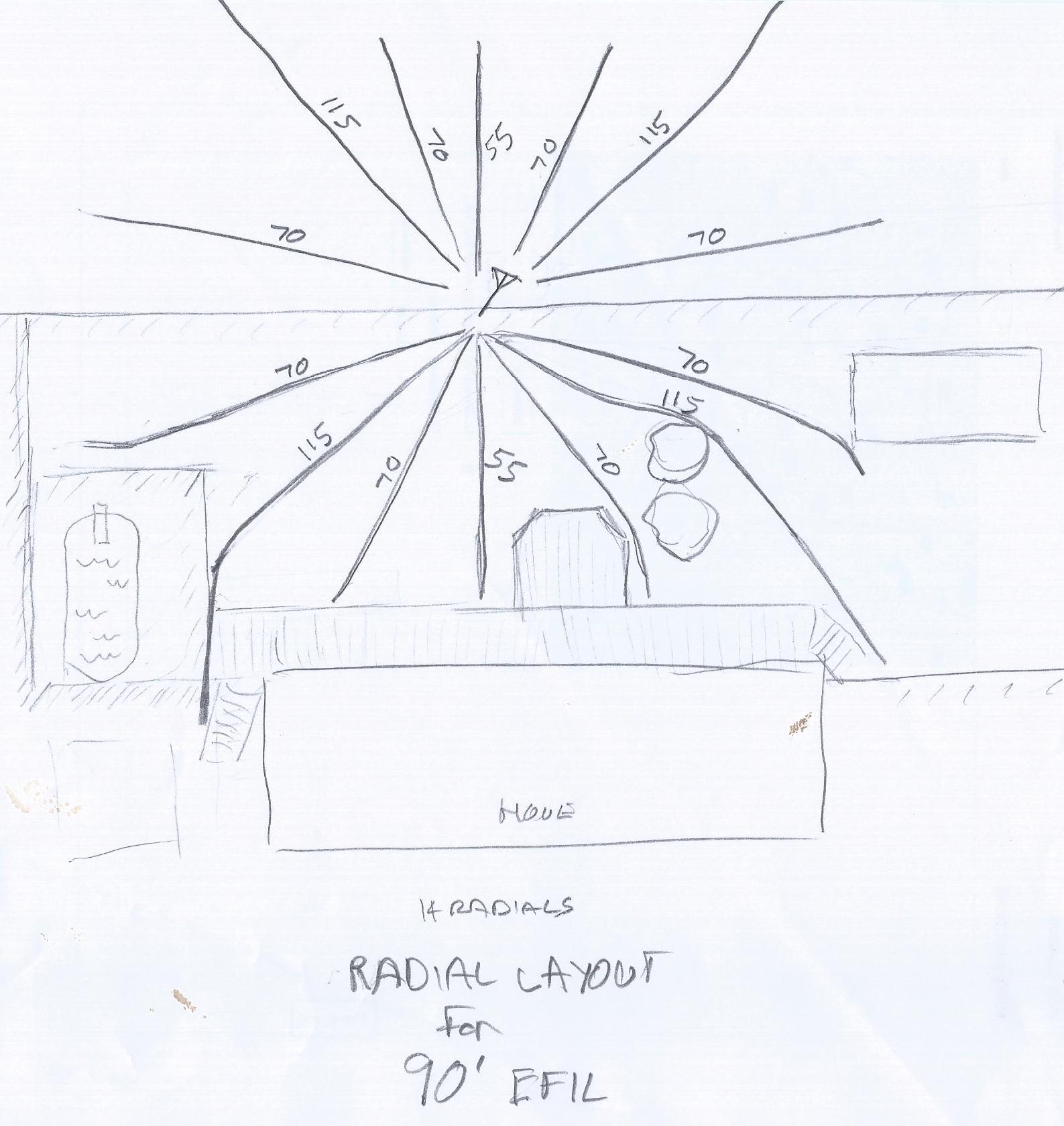
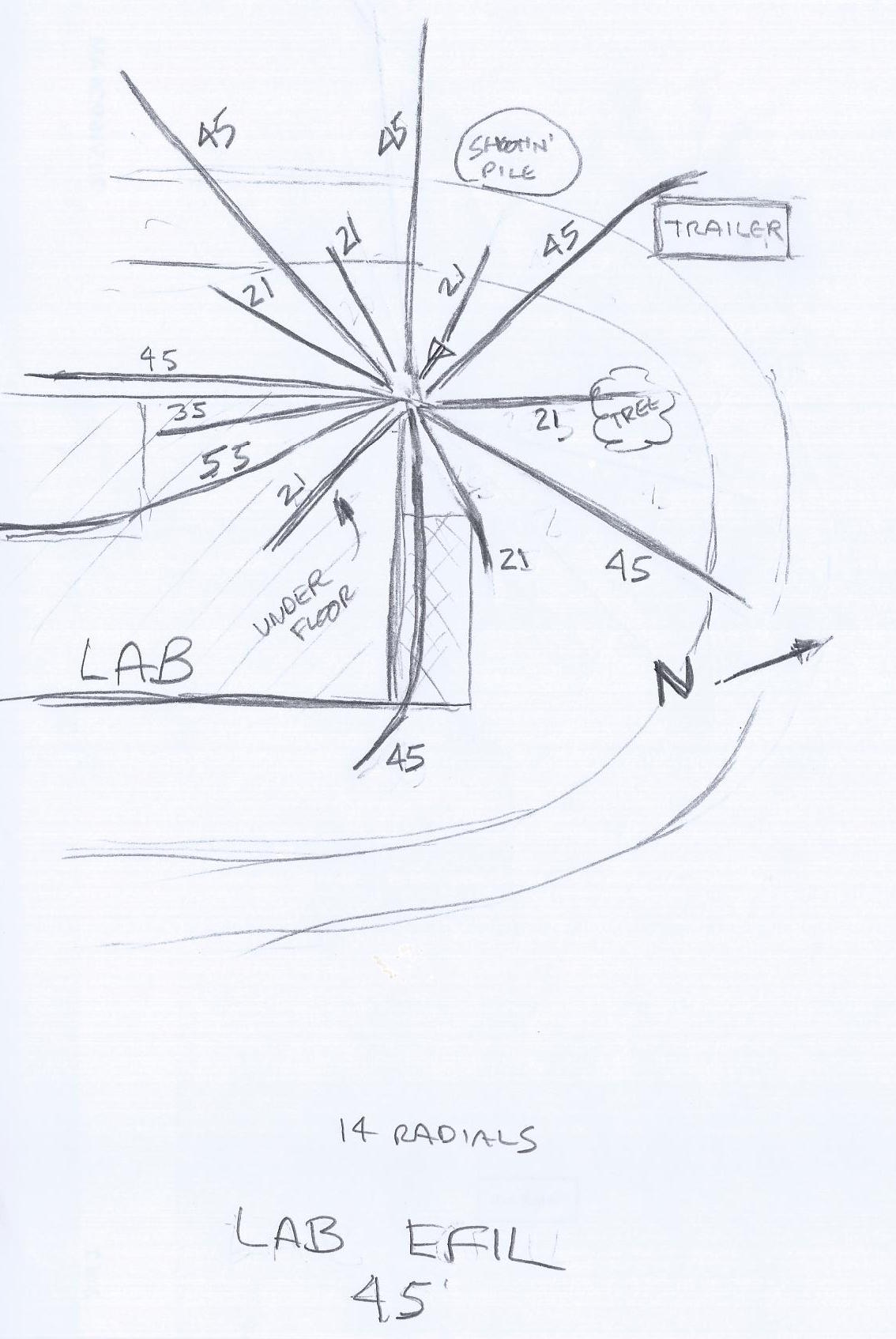
Could you better describe your modeled ground/radial system?
I would love to try it out at my location to see if I can get as accurate results as you are getting.
I use a “broadband ground” consisting of several short grounded wires of various lengths. It’s a Q&D method I use to separate the response of the radiator itself from any “coloration” by an actual counterpoise system. Once the performance of the radiator is explored, the actual radial field could be put back in and characterized to whatever extent the modeling program will allow. It is my understanding (???) that the NEC2 version of EZNec that I use doesn’t do a great job of modeling actual radial fields 🙁
Hi there, did you also determine the variation in feedpoint impedance for the 45ft version ?
btw, great blog.
Thanks Todd. Not sure what you mean by “variation in impedance’? I have some data somewhere showing the plots of the individual units I measured as well as the average, if that’s what you mean.