Excellent technical reference article by Steve G3TXQ:
Amateur Radio (G3TXQ) – Common-mode chokes
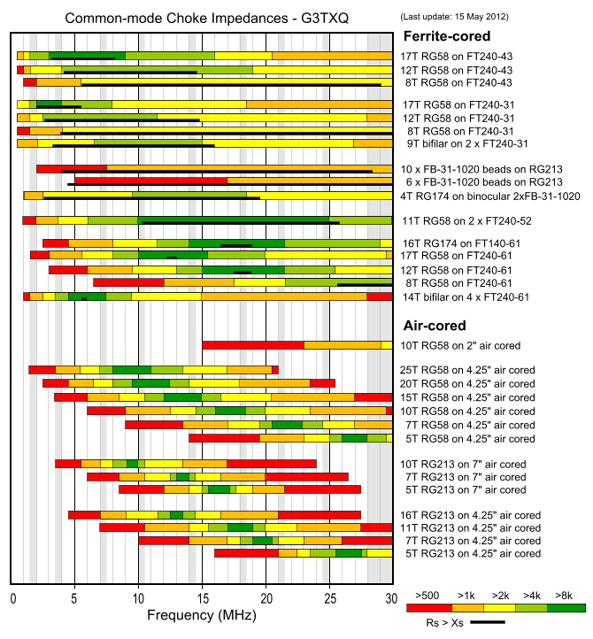
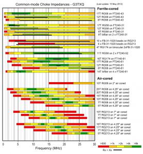
The above chart presents the results of impedance measurements made on a variety of common-mode choke implementations across the frequency range 1MHz to 30MHz. Amateur frequency allocations are indicated approximately by the vertical grey bands.The colours of the bars indicate the magnitude of the CM (common-mode) impedance; however, depending on the style of choke and the type of ferrite material used for the core, that impedance might be mostly Resistive, mostly Reactive, or somewhere in between. The black bars at the bottom of the coloured bars indicate the range of frequencies over which the choke impedance is predominantly Resistive – that is Rs>|Xs|. No black bars are shown for the air-cored chokes because their impedance is almost entirely Reactive apart from a very small band of frequencies around resonance.
Reactive chokes have the disadvantage that they can “resonate” with a CM impedance path that is also reactive but of opposite sign – in some cases actually increasing the CM current flow rather than choking it; see the section at the bottom of this page for a detailed explanation. Resistive chokes have the disadvantage that if they have insufficient impedance to reduce the CM current to a very low value, there may be significant core heating.
Aim to choose a choke which has a high impedance and is Resistive over the frequency range of interest. For high power applications RG400 coax can be used in place of RG58 with little change to the choke impedances.
The method I use to measure choke impedance is shown further down this page. I will add more data as I make further measurements.
Why reactive chokes are undesirable
Let’s take the example of a 20m half-wave dipole erected 30ft above average ground. It is fed by RG213 coax which drops vertically away from the dipole and whose braid is earthed at the “shack end” to a moderately effective 20Ω ground. The centre conductor of the coax is connected to the left-side dipole leg, and the braid to the right-side.
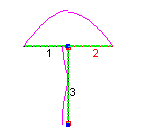 At the feedpoint, current flowing along the inside surface of the braid will split – some will flow into the right-side dipole leg and some will flow down the outside surface of the braid, depending on the relative impedances of the two paths. The impedance of our coax braid path is fairly high – about 28-j200Ω; the -j200 capacitive reactance arises because the coax is short of an electrical half-wavelength. EZNEC predicts that about 0.17A of the total 1A injected at the feedpoint will follow the Common-Mode braid path, as shown on the right
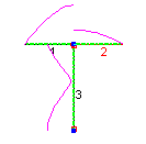 But if we now install a reactive CM choke at the feedpoint, and it happens to have an inductive reactance of +j200Ω, we will cancel the capacitive reactance of the braid path and create a fairly low impedance CM path of just 28Ω; the braid current will then rise to 0.64A – that’s a majority of the current flowing at the feedpoint!
In this example an inductive reactance of +j200Ω is obviously a “worst case” and you would be unlucky if the choke was exactly that impedance; but note that any choke reactance between 0 and +j400 will reduce the CM path impedance – and therefore increase the braid current – to some degree.
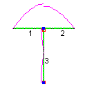 However, if we install a 200Ω Resistive choke at the feedpoint instead of a 200Ω Inductive choke we will effect an improvement, as shown in the third diagram.
As we vary the length of the coax, the braid path impedance changes. When the coax is close to a quarter-wave long the CM path is high-impedance and relatively little current flows along the braid whether we include a choke or not; when it is close to a half-wavelength long substantial current flows if we don’t include a choke. But there is no length of coax where an “unlucky” reactive choke impedance could not make things worse!
The situation gets more complex with a multiband antenna – in fact the potential for a Reactive choke exacerbating the situation on at least one of the bands increases.
However, it’s worth noting that when the reactive component of the CM path impedance exceeds +/-1000 Ω there is also likely to be a large resistive component; this means that reactive chokes may still contribute useful choking impedance provided their reactance is several kΩ.
The following table shows for a range of coax lengths from 20ft to 70ft on this model the braid current without a choke and with a worst-case inductive choke; it also shows the impedance required in a Resistive choke to keep the braid current 30dB below the level of the dipole current.
| Coax length (ft) | Braid current (A) – no choke | Braid current (A) – inductive choke | Choke resistance (Ω) for -30dB braid current (0.03A) |
| 20 | 0.03 | 0.07 | No choke needed |
| 25 | 0.08 | 0.37 | 1200 |
| 30 | 0.17 | 0.64 | 1100 |
| 35 | 0.54 | 0.63 | 900 |
| 40 | 0.14 | 0.39 | 750 |
| 45 | 0.05 | 0.17 | 600 |
| 50 | 0.02 | 0.04 | No choke needed |
| 55 | 0.02 | 0.04 | No choke needed |
| 60 | 0.07 | 0.24 | 950 |
| 65 | 0.16 | 0.5 | 1000 |
| 70 | 0.55 | 0.56 | 950 |
We note that:
- For all coax lengths a Reactive choke has the potential to increase the CM current, sometimes by a very significant factor, unless it exhibits several kΩ reactance
- Different values of choke Resistance are needed to reduce the braid current, depending on coax length
We conclude that a high value Resistive choke is the safe option for all scenarios. We also conclude that Rules-of-Thumb which equate the required choke impedance to some multiple of the differential-mode load impedance are unsound.
Choke impedance measurement
My early attempts at choke impedance measurement used a Vector Impedance Analyser (AIM4170) with the choke directly connected from the measurement port to ground. However it’s not ideal: very high choke impedances are outside the range where the analyser can be expected to be accurate, and despite careful calibration to the measurement plane the analyser always added the equivalent of a few pF of parallel capacitance; this significantly shifts the self-resonant-frequency of higher-Q chokes such as those wound on Type 61 material or air-cored.
It turns out that more accurate results can be obtained by measuring the attenuation the choke introduces when placed between a signal source and a load. So, for instance you could place the choke in series between a signal generator and an RF voltmeter; then, knowing the generator output and the RF voltmeter reading, you could deduce something about the choke’s impedance. However this simple scalar measurement will not tell you anything about the choke’s complex impedance (its resistance and reactance), which as we have seen is vital for a complete understanding of how well it will perform.
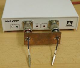 Fortunately, a 2-port Vector Network Analyser can measure both the magnitude and the phase of the attenuation introduced by the choke, and that allows us to fully determine the choke’s complex impedance. I use a VNA2180 in the arrangement shown on the right. The jig typically adds the equivalent of 0.2pF or less of parallel capacitance.
The ports of the VNA are connected to a test jig comprising two BNC male connectors mounted on a small piece of PCB material; “crocodile clips” soldered to the BNC centre pins allow the choke to be connected in line.
The VNA is first calibrated with the two clips shorted. Then the choke is connected between the clips, and a VNA measurement scan made between the required frequencies. The resulting S21 Amplitude and Phase data is then transferred to a spreadsheet to calculate the choke’s complex impedance.
9,954 total views, 3 views today
This is very interesting but way over my head. As a real old man it would be nice to be able to plug in my data for my antenna and be able to get a response as to what would be my best bet to use. i:e G5RV jr at 50 ft, inverted V formation with ends about 12 ft off the ground feeding the ladder line with 50-ohm coax through a 4:1 balun. and a current balun wound 12 turns of RG 8X about 12″ in diameter.
Or when I add a 90 ft extension on each end, (not changing any ladder line) making it a 160-meter dipole what else should I change. (the thing works well on 15, 20 and 40 as well)