We look at the magnitude of the impedance of an EFHW “antenna” for short counterpoise lengths.
Thanks to Jon AF7TS for the suggestion and discussions that led to this article.
In engineering we sometimes can not directly calculate a value, often when a “divide-by-zero” shows up, as when we try to calculate an impedance wiith a zero length element. However we can usually still tell what that value will be by sneaking up next to it and determining what it asymptotically approaches.
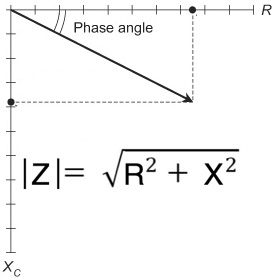 The Magnitude of the Impedance is |Z|= SQRT ( R^2 + X^2 ) as shown above, and we fill in the values by modeling an antenna which on the one side is a half wave of wire and on the other side is a wire of decreasing length.
Note that the point of this article is not to provide definitive values of impdances vs. length (since many factors influence this result), but rather to show what happens as the counterpoise length approaches zero.
We model a 67 ft EFHW wire for example, and vary the “counterpoise” from 2 ft down to 0.01 ft and get the following results ===>
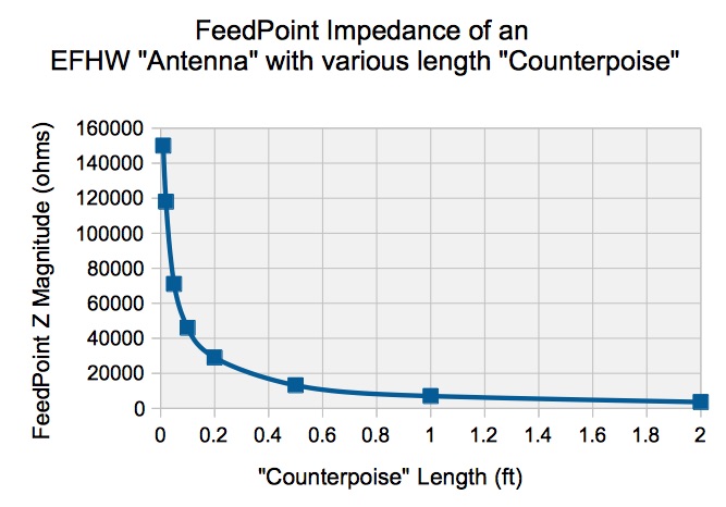 We can see that the magnitude of the impedance approaches infinity as we make the counterpoise progressively shorter.
Steve AA5TB has presented a similar graph, showing instead both R and jX. As we can see, the reactance X is capacitive, as expected. We can see that it is the capactive reactance that is responsible for the magnitude of the impedance shooting off toward infinity. ===>
________________________________TAKE AWAYS
- As the “counterpoise” is made progressively smaller, feedpoint impedance rapidly approaches infinity.
- At zero counterpoise length, impedance is infinite and no current can flow, necessarily meaning that all working “end-feds” have a counterpoise of some sort, whether formally designed into the system or not.
- Without a significant formal “counterpoise”, we have the often undesirable case of the coax shield serving as most or all of the ad-hoc counterpoise; the “other half” of the antenna.
Dave Benzel- KD6RF – 2017 Jan 1
13,571 total views, 4 views today
David, While playing around on WSPR tonight I happened to look up your call on QRZ.com and discovered you worked at LLNL. I worked there my self from 1963 to 1993. I was a Senior Engineering Associate in the Field Test Systems Div. I now live in Genoa, NV.
73 Jim
Outstanding Jim! It wouldn’t be out of the question that we had bumped into each other.
73 – dB
Since…xxx.. no, let’s assume you have a half wave of wire hanging in space to some extent at least, it will have radiation resistance. Or the reciprocal of conductance. Won’t that lower the Q factor and allow some current into the end of the wire even with infinite resistance at the other terminal where the counterpoise goes?
Well, not sure exactly what you are saying, but you have answered part of your own Question. if you have infinite resistance, you can calculate the current flow by our standard old friend – ohms law. I = E / R ===> for infinite resistance, I = 0