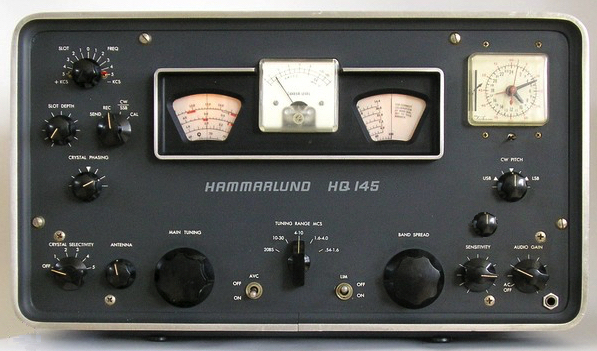
In this article we will look at a few of the big deficiencies of the Hammarlund HQ145 general coverage shortwave receiver, and put in some fixes. CW/SSB reception with AGC and S-Meter, stability issues, bandspread, and sensitivity on the high band will be addressed.
Once modified, the HQ145 turns out to be a very nice ham and general coverage receiver all the way up through 10 M. It’s like my wife: attractive, capable, and a pleasure to be with. Or, it could be said Sweet, Sensitive, and Stable!
CW/SSB OPERATION WITH AGC AND S-METER
One of the inelegancies of this era’s typical receiver was the lack of a proper product detector with AGC functionality – when switched to CW/SSB, the AGC would be disabled and the user had to adjust RF and AF gains to hear an undistorted signal. In addition, the S-Meter was disabled.
One way to overcome this limitation with minimal re-work of the receiver’s circuitry is to implement an audio-derived AGC. Most circuits found on the web seem to suffer from stability and “pumping” problems. The solution was to design and employ an AGC filter along the lines of the “lead-lag” filter often used in PLL loops.
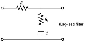 The circuit below provides full functionality of the receiver’s switches, controls, and S-Meter; with carrier-derived AGC when in REC/AM mode or audio-derived AGC when in CW/SSB mode. The “lead-lag” filter is a standard fast-attack slow-decay design as set by the 0.1 uF capacitor and associated 27K and 10M resistors.
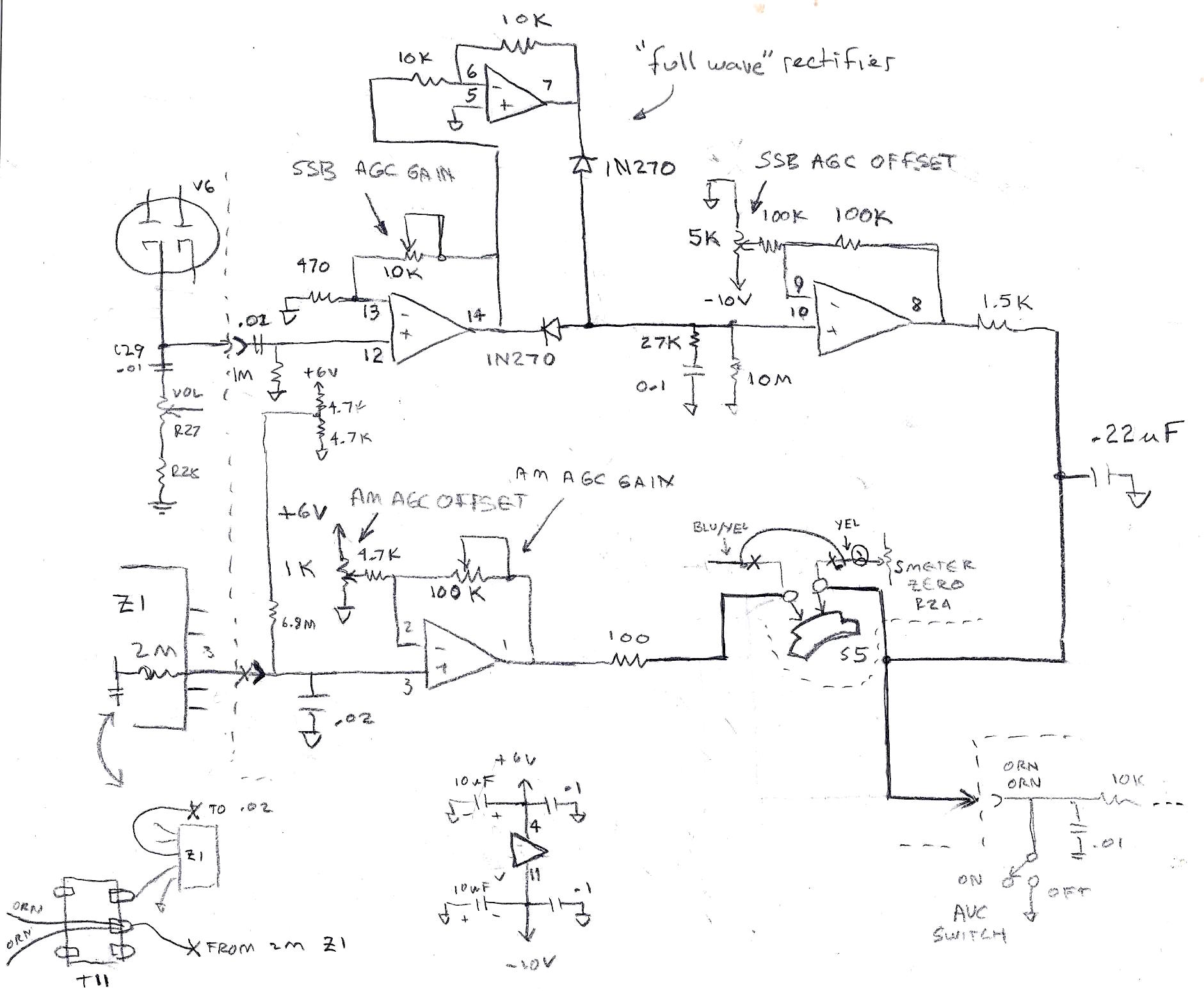
Audio is taken from V6’s cathode output, is amplified, full-wave rectified, filtered, and then buffered by the op-amp circuitry. Calibration of “Gain” and “Offset” are required for proper operation, and is accomplished with a signal generator or with on-the-air signals.
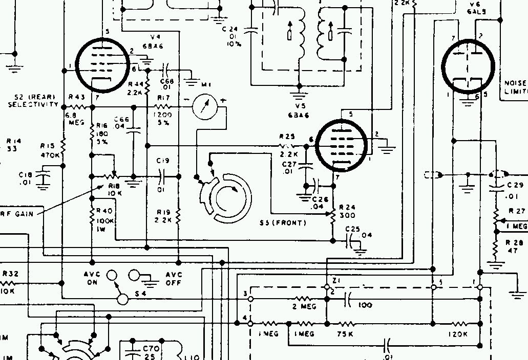
Note that at S5, we remove the S-Meter wiring from the switch, and connect the two wires together permanently. This is what we want since the S-Meter now works properly for ALL modes. We now use the freed up switch contacts to over-ride the new audio-derived AGC, and instead use the existing carrier-derived AGC (ALC) when not in CW/SSB mode.
Measured voltage values of AGC (ALC) and detected audio for the new audio-derived AGC (in CW/SSB mode) are shown below. These voltages are very close to the values as produced by the original ALC circuit when in REC/AM mode:
| S-Meter Reading | V AGC (Volts) | V Audio p.p. (Volts) |
| S0 | 0.24 | 0.02 |
| S1 | 0 | 0.3 |
| S5 | -1.09 | 1.4 |
| S9 | -2.14 | 2.7 |
| S9 + 20 dB | -2.92 | 3.7 |
| S9 + 40 dB | -4.02 | 4.5 |
| S9 + 60 dB | -5.35 | 6.0 |
All of this circuitry is hidden under the aluminum cover on the inside rear chassis wall.
STABILITY ISSUES
Two main sources of frequency instability are addressed here – One is “warm-up” drift, which is mitigated with a simple always-on filament supply for the VFO and 1st Mixer tubes. A second source is filament voltage change with varying line voltage, which is solved by using a new regulated DC supply for the VFO and first Mixer tubes.
This modification alone promoted the HQ145 from near worthlessness on the upper bands with several KHz to a few 10’s of KHz drift, to a very usable few tens to a few hundred Hz of drift under warm-up and line-load conditions.
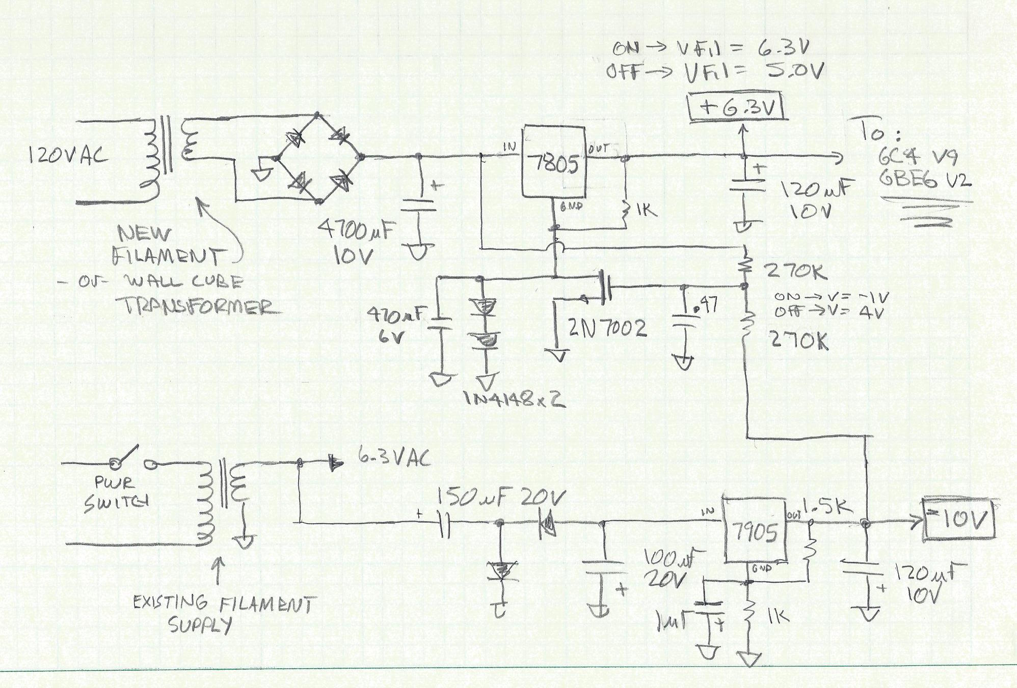 This new filament supply (for the VFO and 1st Mixer tube filaments) is regulated DC at 6.3 Volts when the receiver is turned ON, and regulated down to 5 volts (presumably to extend tube lifetime) when OFF. This unit also supplies the +6.3 Volts (called +6V) and the -10 Volts for the other modifications.
The transformer is mounted on the inside rear chassis wall. Semiconductors are “hidden” underneath the other components built onto a new terminal strip mid chassis.
BANDSPREAD
On some versions of the HQ145, Hammarlund added an unlabeled sort-of calibration and mechanical bandpread control. On my unit, it simply wasn’t all that consistent or useful.
Here we show that it’s a simple matter to replace the mechanical control with a compression type mica trimmer capacitor. It may be that a small conventional unit could also be used, but I found the multi-turn functionality of the compression mica trimmer to be more useful from 40 M up through 10 M. One pair of plates is used, and the unit is simply wired in parallel with the Main VFO tuning capacitor.
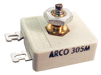 A longer brass screw was used in place of the trimmer’s standard adjustment screw. Once tightened in place, a 1/4 inch threaded standoff was screwed and tacked onto the compression mica trimmer’s new threaded screw to allow for the use of the original knob.
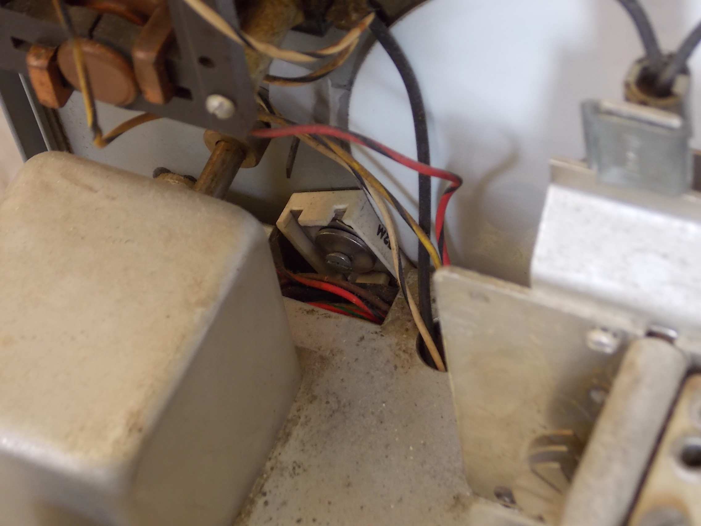
The compression mica trimmer is snuggled into the stock chassis cutout in the stock location.
SENSITIVITY ON THE HIGH BAND
Hammarlund designed double conversion architecture into the HQ145 on the highest band for better image rejection. Unfortunately this was done by using a penta-grid converter tube as the first frequency mixer which was used as a low gain RF amplifier on the lower bands. Therefore sensitivity suffers on the higher bands where it is needed most.
The low gain problem was solved by building in an FET amplifier at the first IF of about 12 dB gain. Receiver noise figure was good enough as-is such that further RF amplification was not required. 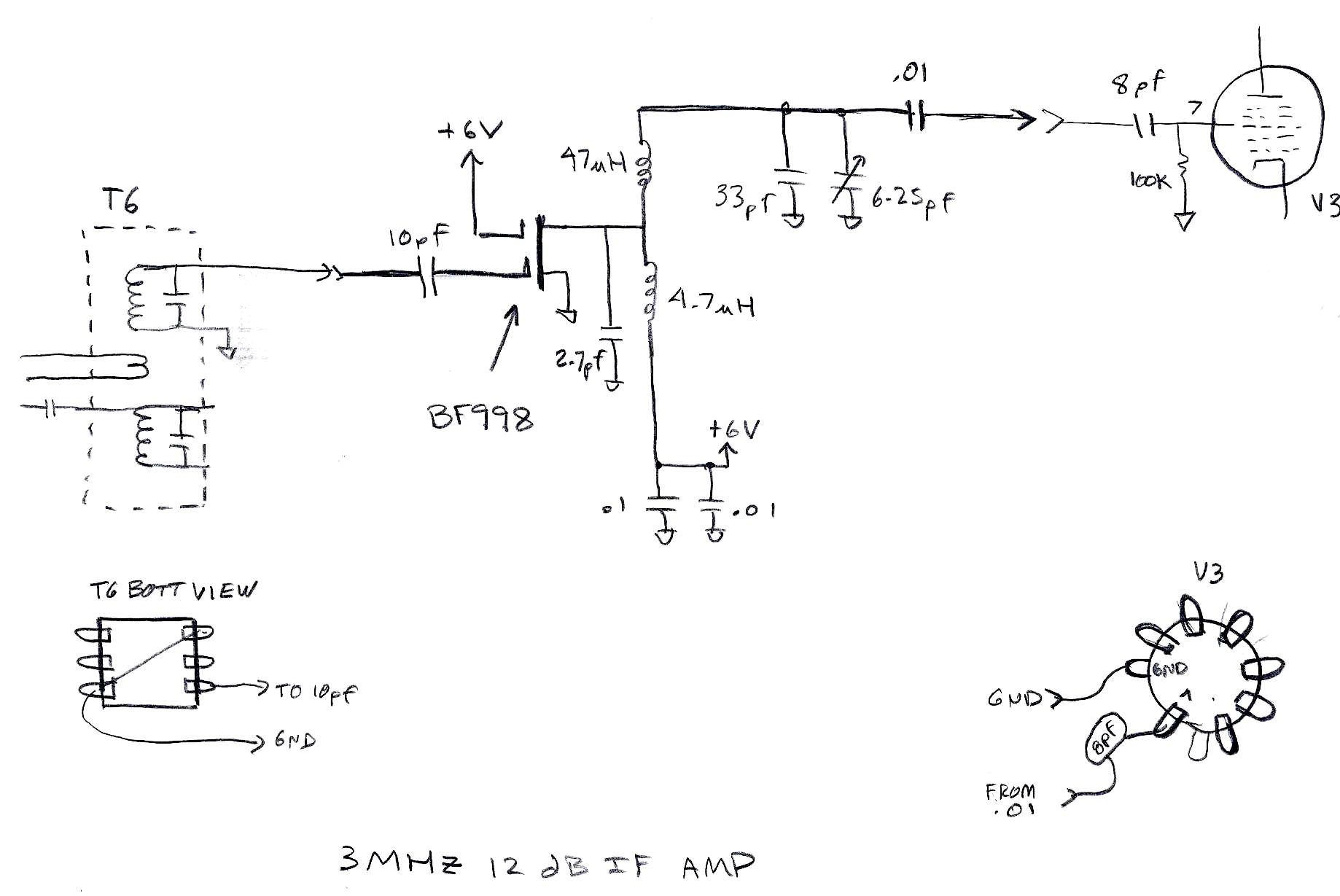
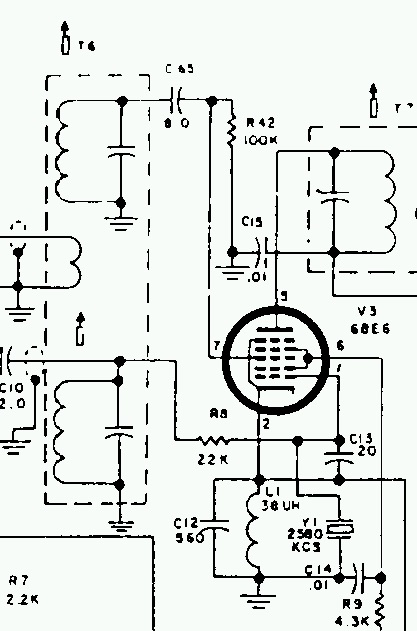
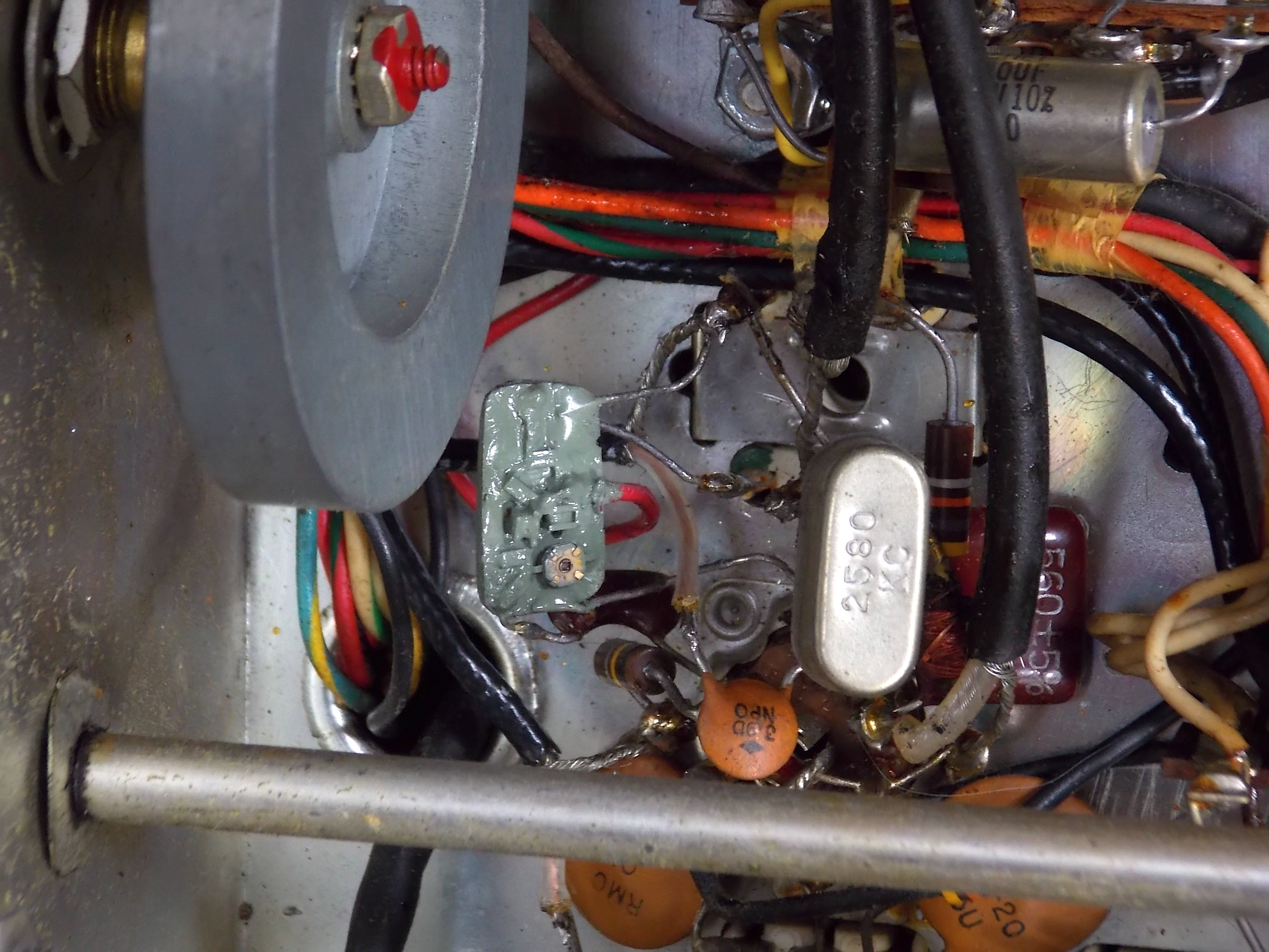
The unit was constructed on a small circuit board using surface mount components. It was then encapsulated in epoxy and painted drab green to resemble a “hybrid” commonly used in this era.
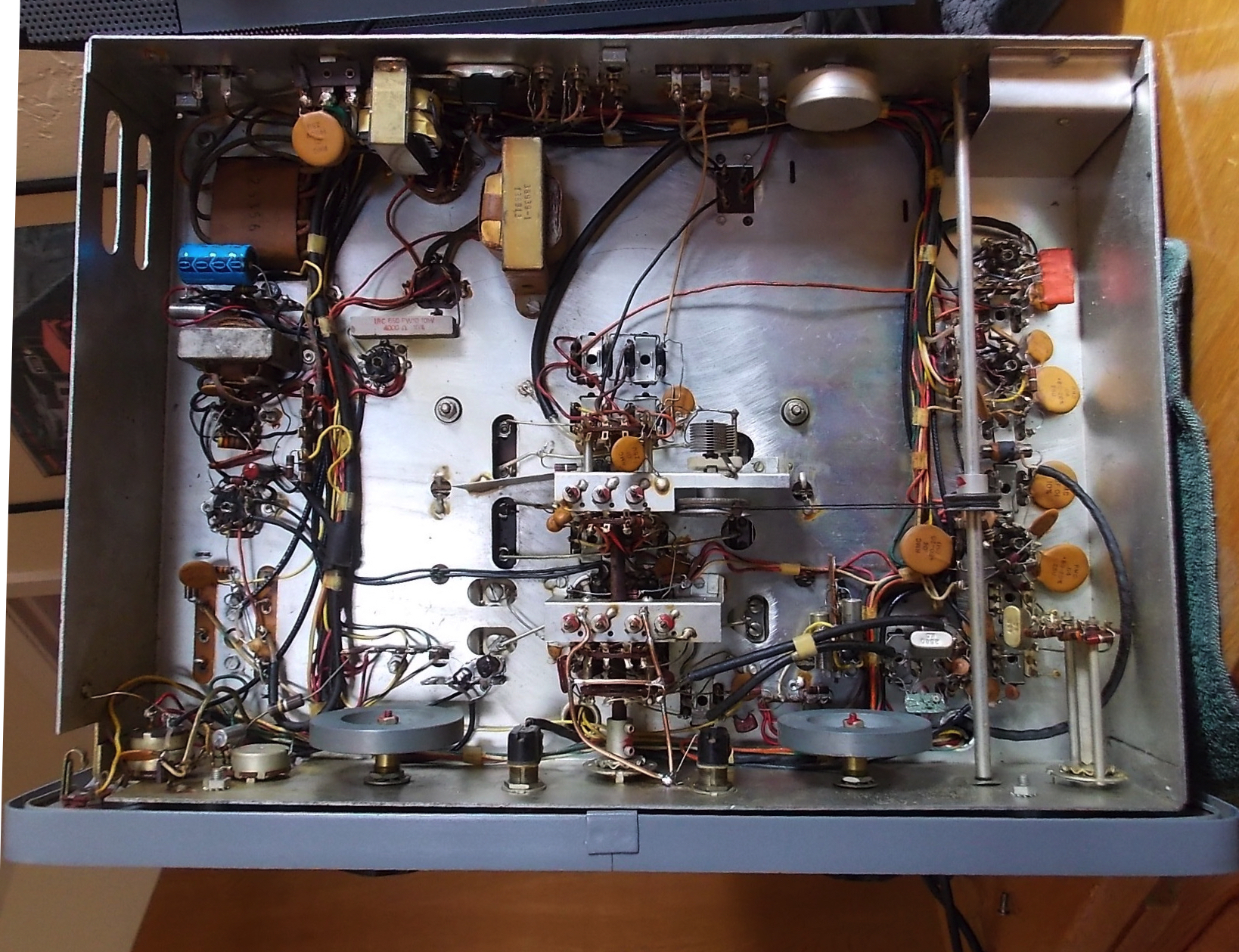
BOTTOM VIEW
Casual inspection shows nothing glaringly out of place or period, with the possible exception of modern-ish looking electrolytic capacitors.
Dave Benzel – KD6RF – 2017-Jan-6
13,536 total views, 9 views today
Hi. I’ve had a 145 for about 20 yrs now. When a novice in 65 and after I got my general license used an hq 150. I really love using tube stuff. I was stunned to run across your site about the questions I always had about my 145. I would like to apply your circuits to mine. I was studying the agc/ s meter diagram. what is z1 and /or the ic you used? I racked my brain as to why did they (Hammarlund) doubly converted the signal when you lost so much gain on the 10 to 30 setting. Thanks for your site. I hope you will reply. I love these old radios that are still comprehensible to the old guys. 73. Rod
Nothing like the classic beauty of one of these tube rigs is there…. 🙂 And Hammarlund relly got the “feel” right with the fly-wheeled tuning knobs/shafts.
The Z1 is the “hybrid”, and in my chassis-bottom pic above, it’s the orange rectangle in the upper-right corner.
The op-amp used was an old 741 variant. Almost anything can be used as long as it can handle the +6 and -10 V supply. Naturally, using a run-of-the-mill low freq op-amp will help avoid any potential stability issues.
I imagine Hammarlund went double-conversion on the high band to improve image-rejection, but I guess they just couldn’t pull the trigger on adding one more gain stage. Fortunately we got lucky with their design, and they made it trivial for us to add our own gain stage.
GL Rod – 73 – dB
Hi. I’m still working with my hq145. My question is do you have place to buy your parts? I’m having a little trouble locating them. Thanks, Rod
For new stuff I used the standards – Mouser, DigiKey, Newak, etc… For the less usual and older stuff, I scrounge around on eBay.
thanks for the quick reply. I am not real up on solid state terms and parts but will endeavor to replicate your improvements. many thanks. 73, RD
Hi. Don’t mean to bother you with this but wondered if you have solved the drift problem with Rangers and Valiants aside from an outboard vfo? thanks. 73, RD
once again I ask a question because of my ignorance mostly…I looked up the 741 op amp and it only has 8 terminals. am I not understanding this? I hope you are able to set me straight. Thanks again. 73 RD
hi. wonder if you received my questions on the modifications on the hq 145. please let me know….if you did not get them i will repeat them. thanks again. you are a genius. 73, Robert
Just us as many of the op-amp sections as you need to implement the circuit.
Hope this helps- – 73 dB
ok. thanks again for your reply. I’ll be giving it a try. You are one smart feller. thanks. 73 Robert