Often one sees characterization and loss measurement of UNUNs using an SWR measurement of the UNUN when terminated in it’s transformation resistance, or with the “back-to-back” 2-x-Loss method. Each method reveals something about some quality of the UNUN, but neither method tell us much about how much power the UNUN will deliver to the actual antenna.
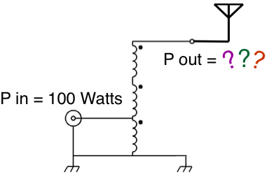 In this article I will show a simple method of measuring actual UNUN losses into the actual load impedances that the UNUN will see in service.
- Construct Antenna and UNUN “Z Clips”, and Measure T-Tuner Losses Into Actual UNUN Impedances as Loaded with Actual Antenna Impedances
1) We construct “Antenna Z Clips” for each band corresponding to the load impedances of the antenna.
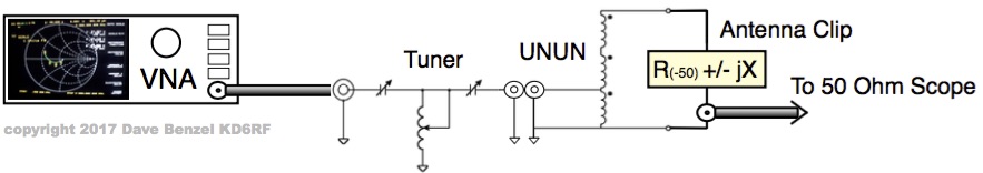
2) We connect an “Antenna Z Clip” to the UNUN, and measure the impedance at UNUN input.
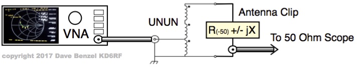 3) We construct another set of “UNUN Z Clips” for each band corresponding to the impedance presented by the UNUN when connected to the antenna impedance.
4) We connect an “UNUN Z Clip” to our T-Tuner, and carefully set the T-Tuner to 50 ohms.
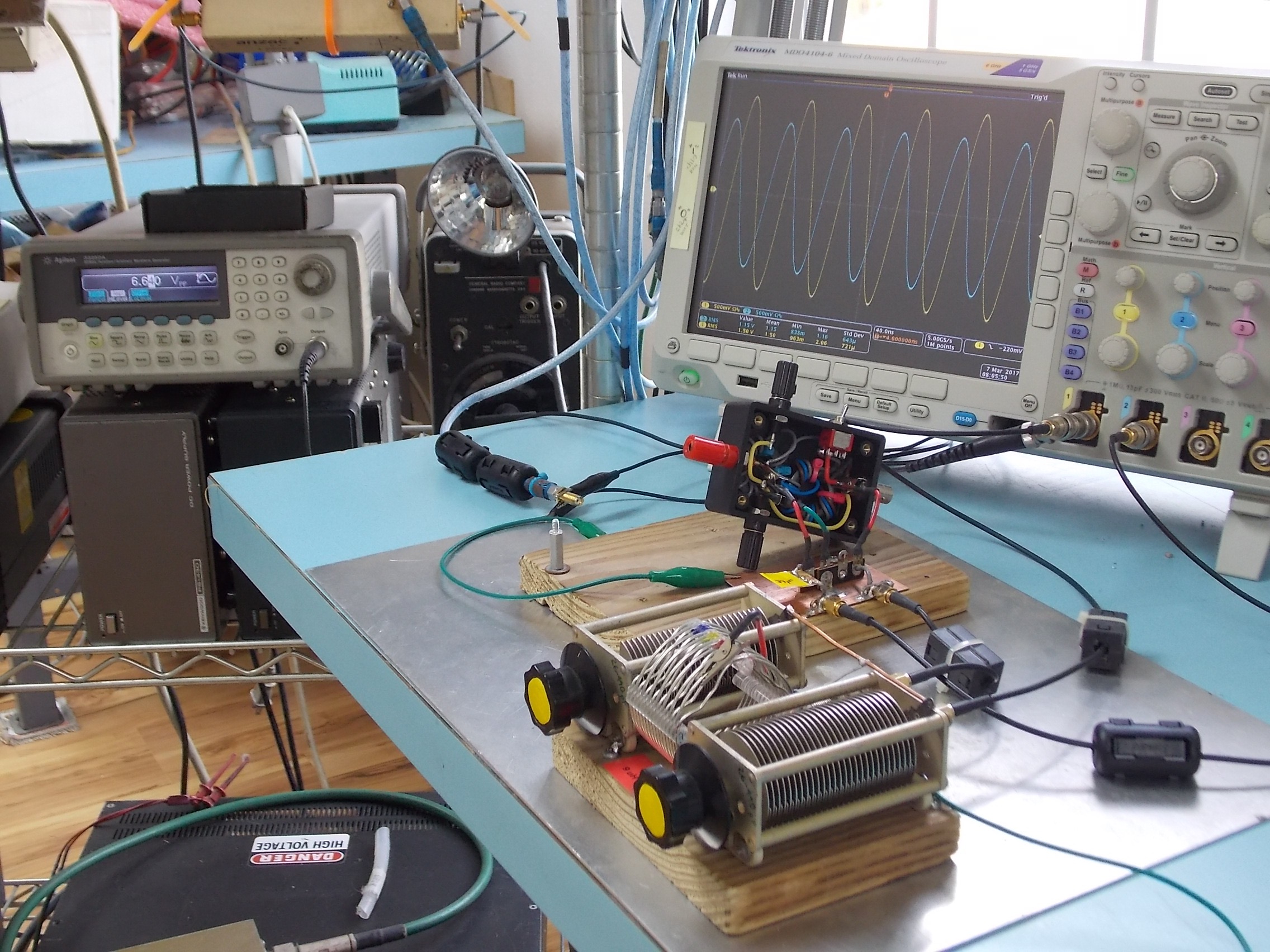
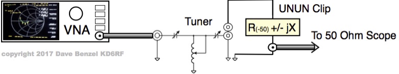 5) We measure the loss through the T-Tuner by measuring input voltage/power and output voltage/power with a signal generator and a meter or oscilloscope. When presented with the Z of the “UNUN Z Clip” (the impedance that the UNUN will provide when connected to the “Antenna Z Clip”), the real-world T-Tuner Loss for our test setup is simply Pout / Pin.
- Measure Actual T-Tuner PLUS UNUN Losses Into Actual Antenna Impedances – Subtract To Isolate Out Actual UNUN Losses
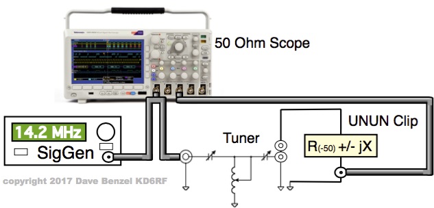
1) We connect an “Antenna Z Clip” to our UNUN which is in turn connected as the load for our T-Tuner, and carefully re-tweak the T-Tuner to 50 ohms if needed.
 2) We measure the total loss through the T-Tuner and UNUN combo by measuring input voltage/power and output voltage/power with a signal generator and a meter or oscilloscope. When presented with the Z of the UNUN connected to the “Antenna Z Clip”, the real-world T-Tuner Loss PLUS UNUN Loss for our test setup is simply Pout / Pin.
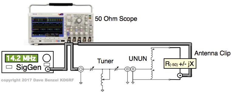 3) We subtract the T-Tuner Loss (as measured in the previous bulleted section) from the T-Tuner Loss PLUS UNUN Loss, leaving us with the real-world UNUN loss.
EQUIPMENT REQUIRED
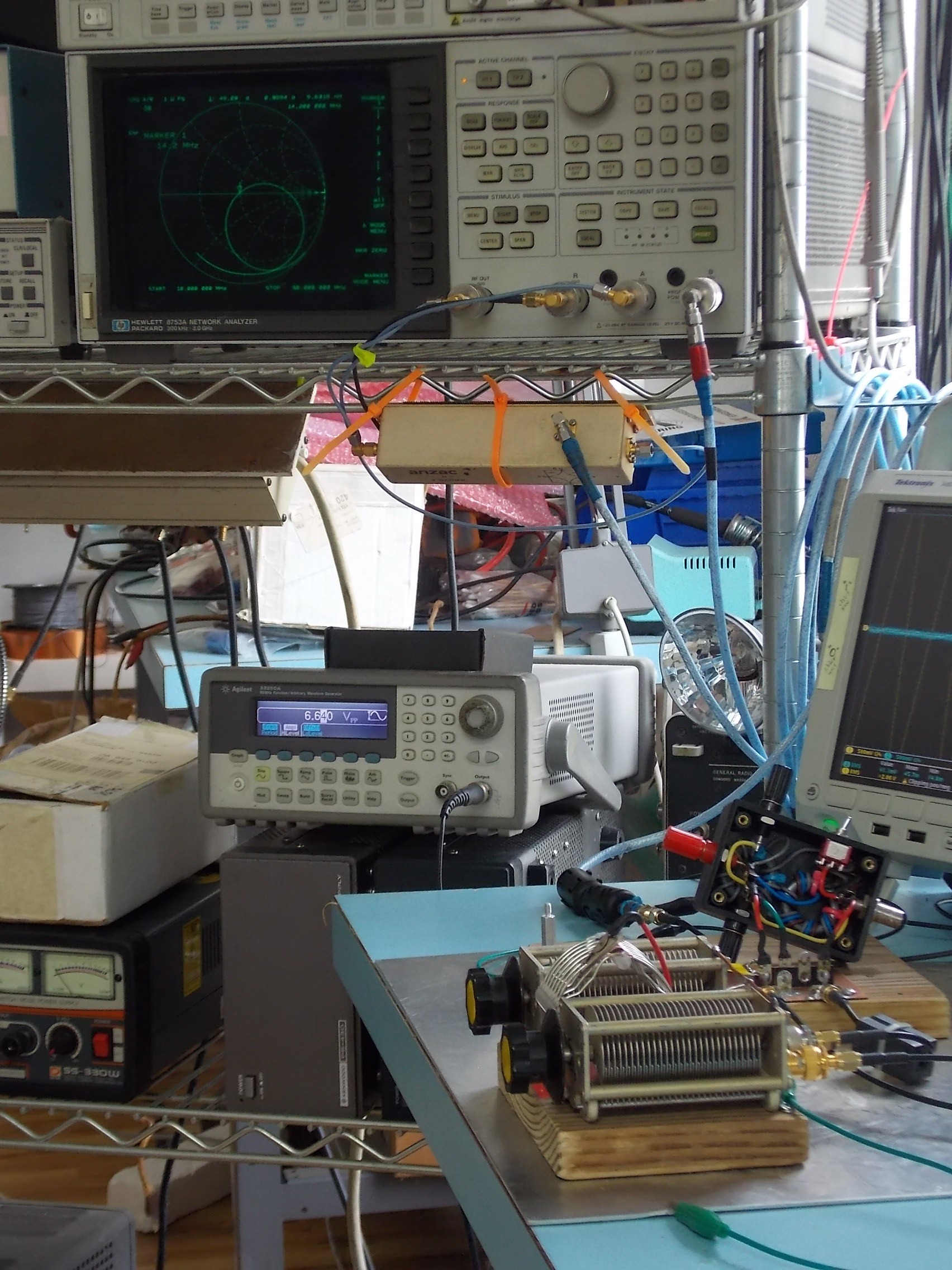
A VNA (vector network analyzer) is required to measure complex antenna impedances, UNUN input impedances, and matched T-Tuner impedance. A real-time scanning type saves time when zeroing in the T-Tuner onto a 50 + j0 match. For these tests, I use my trusty HP8753 3 GHz VNA which, along with cockroaches, will outlive the human species by millions of years.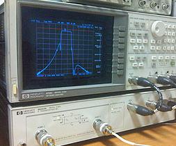 A T-Tuner or other general purpose matcher.
A signal generator to provide a CW signal into our 50 + j0 T-Tuner input.
 An oscilloscope or meter to accurately measure the input voltage to the T-Tuner and the output voltage from our test setup.
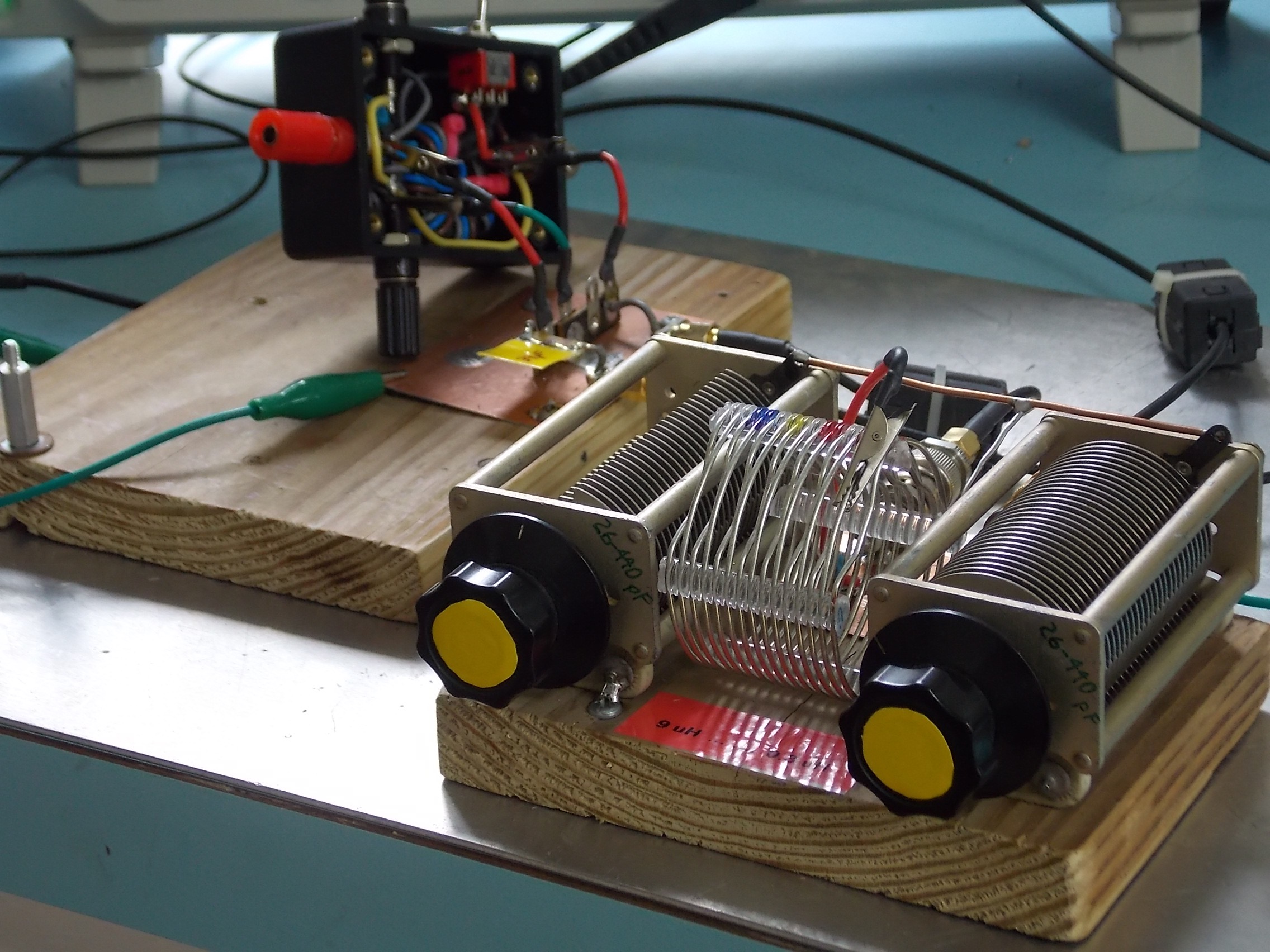
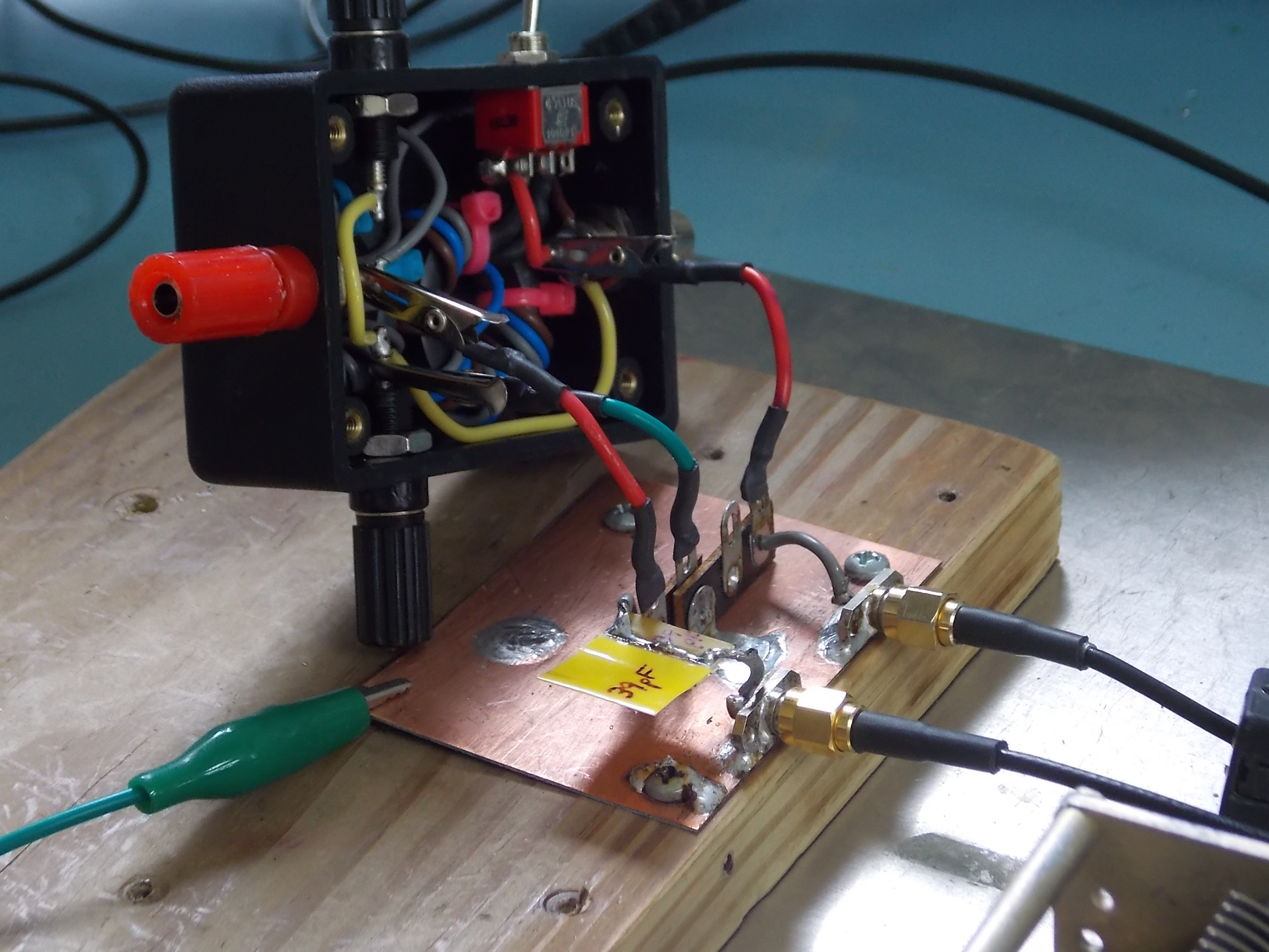
 A test setup that allows us to change “Clips” and UNUNs easily. The test setup needs to have short lead lengths and low parasitic capacitances especially on the 50 ohm output measurement port. A simple setup is fine that uses clip-leads where non-critical, but short leads and good quality connections and connectors where required.
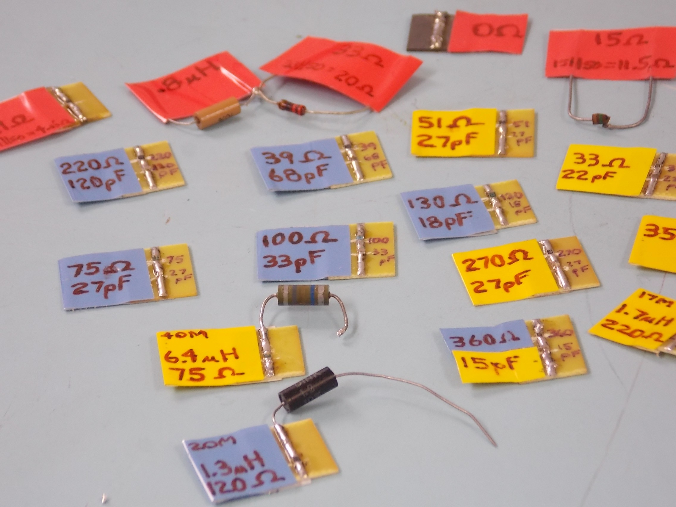
THE “CLIPS”
The real part of the impedances that we construct “Clips” for can be greater than 50 ohms or less than 50 ohms.
For those greater than 50 ohms, we simply solder components in series with the 50 ohm output port to the meter or oscilloscope to comprise the desired R +/- jX. Naturally, the resistance soldered onto the “Clip” is the total resistance required minus 50 ohms. For example, here is an “Antenna Z Clip” representing an antenna impedance of 83 – jX ohms (33 ohms + 50 ohms = 83 ohms):
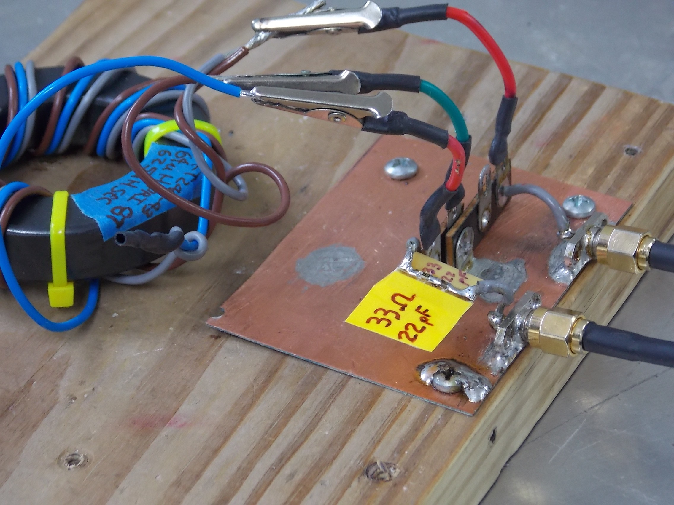
For this case, the voltage applied across the total resistance is found by dividing the voltage measured into 50 ohms by the divider ratio:
Vtotal = Vmeas / DivRatio
where DivRation= 50 / Rtotal = 50 / (Rclip + 50)
and Pout = Vtotal^2 / Rtotal
For those less than 50 ohms, we use a 2 piece “Clip”. Using the shortest leads possible, the resistance is solder in parallel with the 50 ohm output port to the meter or oscilloscope. Naturally the “Clip” resistance is chosen so that the parallel combo is equal to the real part of our desired R +/- jX. The reactance is then placed in series with this paralleled output resistance combo. For example, here is an “UNUN Z Clip” representing an UNUN impedance of 24.7 + jX ohms (50 ohms || 49 ohms = 24.7 ohms). The resistance is soldered parallel directly from output port SMA connector to ground, while the series inductor is soldered to the rest of the test jig:
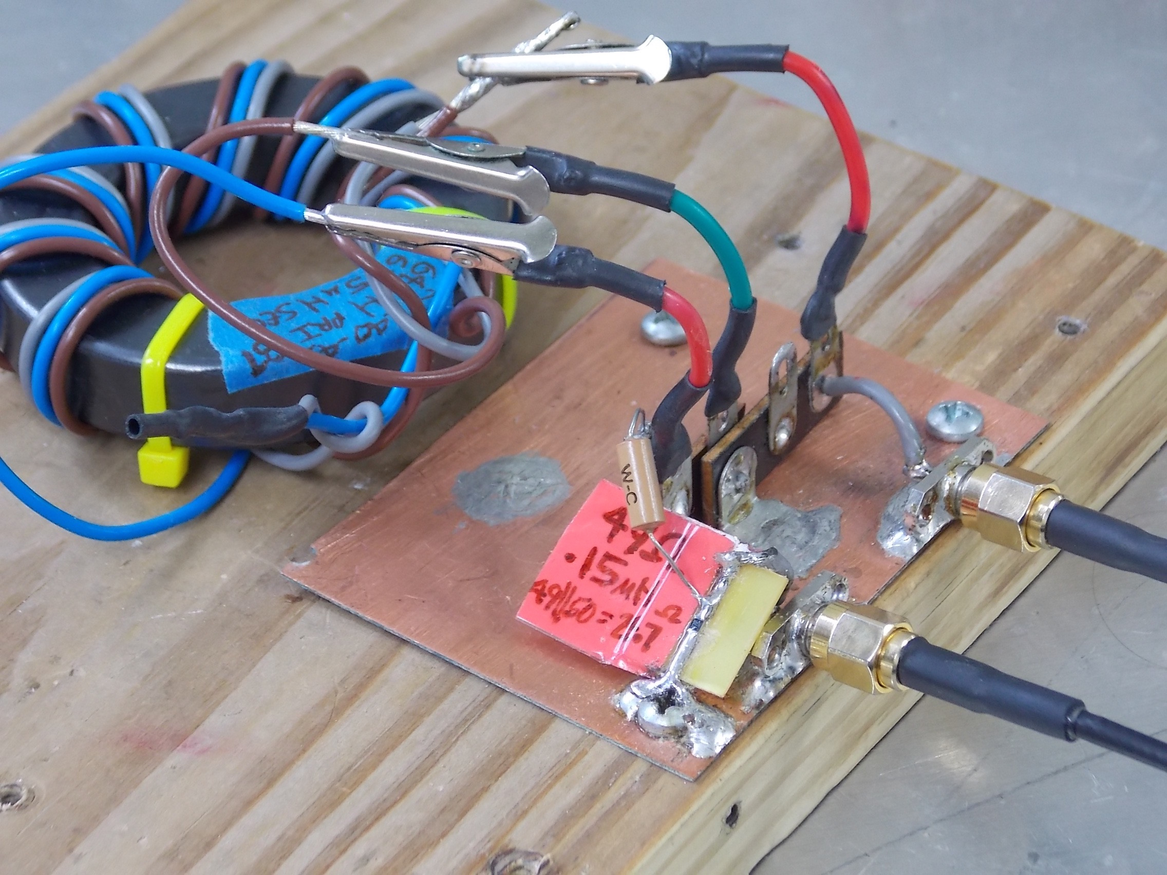
For this case, the voltage applied across the output resistance is measured directly by the 50 ohm measurement system:
Rout = (Rclip x 50) / (Rclip + 50)
and Pout = Vout^2 / Rout
The test setup shown above has been “solid” for antenna impedances lower than approximately 1000 ohms at frequencies up to 54 MHz. Naturally, any project such as this would require true error analysis to get us to a more well-characterized state than simply saying “solid”. But in the mean time, we have a test setup for measuring reasonable loss values that actually address the issue of UNUN losses into real-world antennas.
Thanks to Owen VK2OMD for reminding us that, if we have access to a true VNA with 2 port capability, then we can use the S21 measurement rather than using a signal generator and meter or scope (of course we still account for the power dissipated in the “Clip’s” resistance and mismatch loss). Owen has more info on similar topics on his website ===>
http://owenduffy.net/blog/?p=9624
http://owenduffy.net/blog/?p=9592
And in addition, a handy calculator for Calculating VSWR and Return Loss from Zload (or Yload) ===>
http://owenduffy.net/calc/ZY2Vswr.htm
Copyright Dave Benzel – KD6RF – 2017-Mar-2
5,515 total views, 2 views today