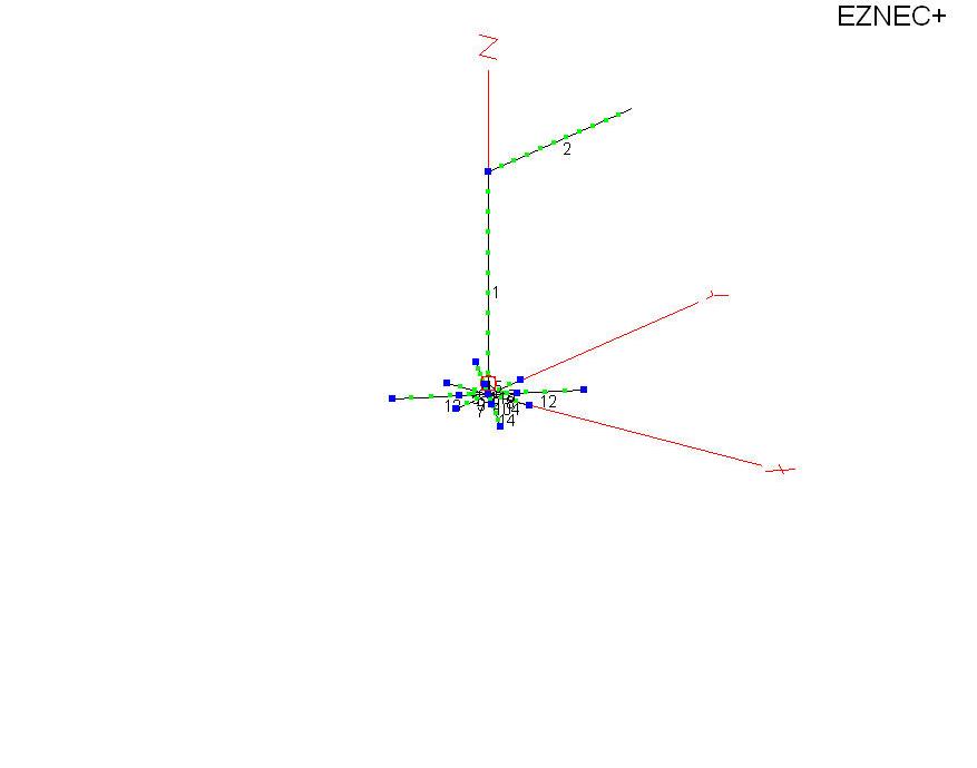
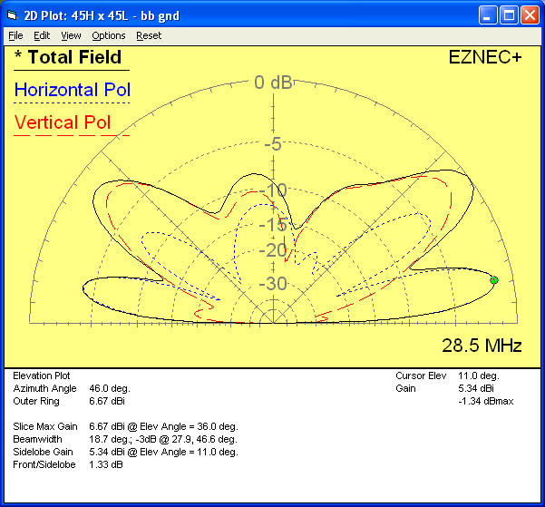
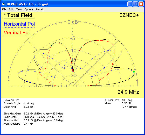
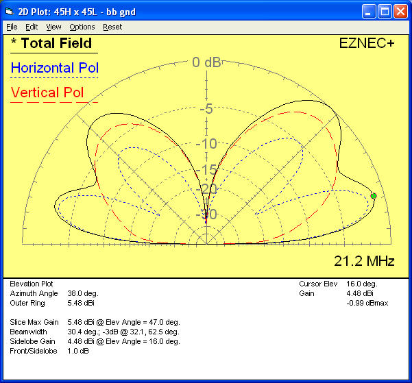
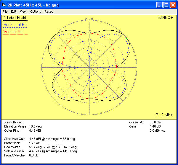
Below are presented the results of EZNec modeling of a 90 ft long End/Base-Fed Inverted-L, 45 ft high and 45 ft across. Elevation patterns and Azimuth patterns at the peak of low angle radiation are plotted for all ham bands 160 Meters through 6 Meters.
For modeling purposes, a multi-connection distributed grounded counterpoise is used. This empirical structure provides a reasonable broadband counterpoise over the frequency range of interest.
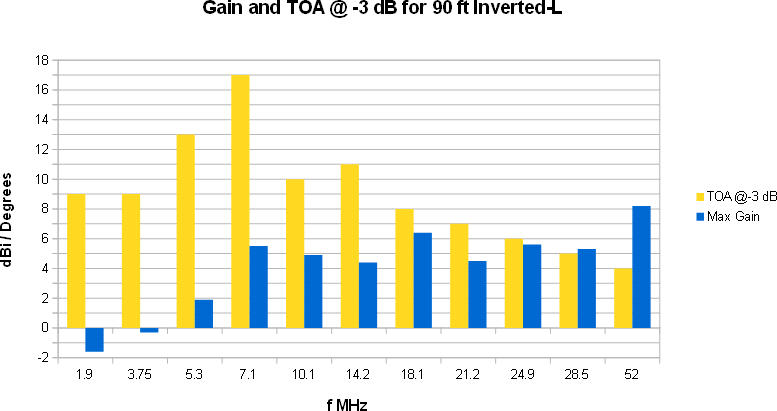
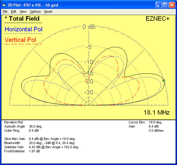
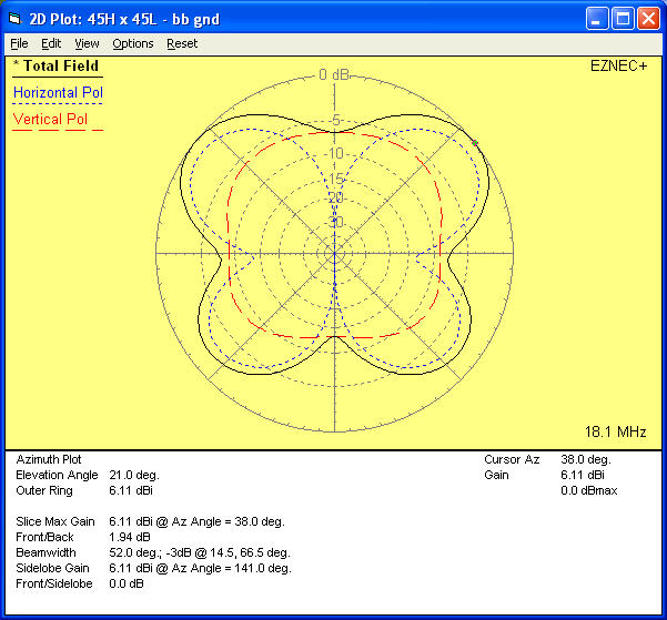
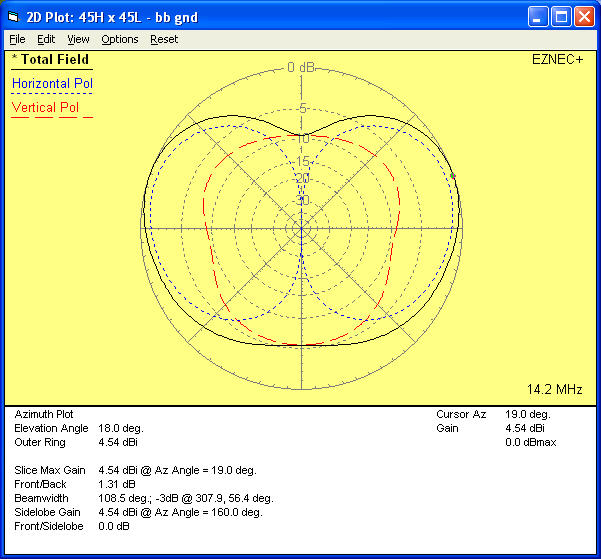
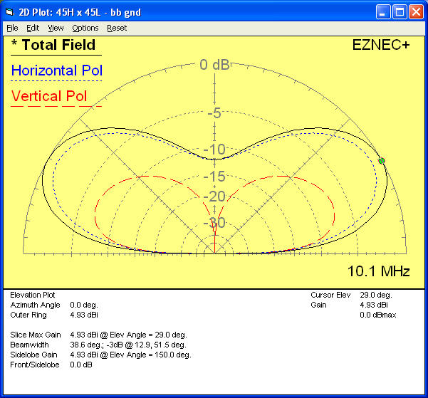
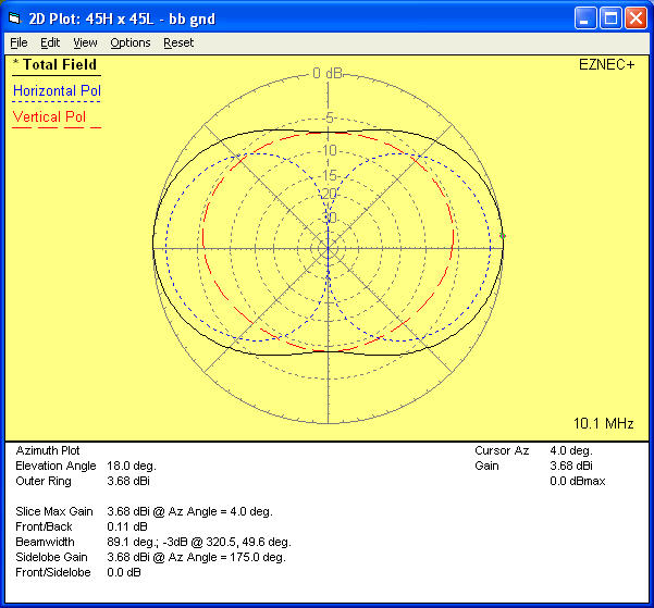
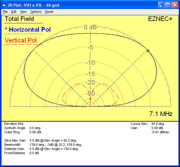
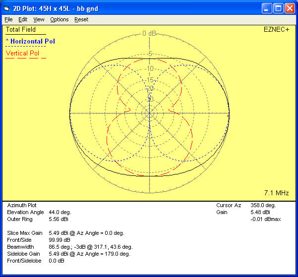
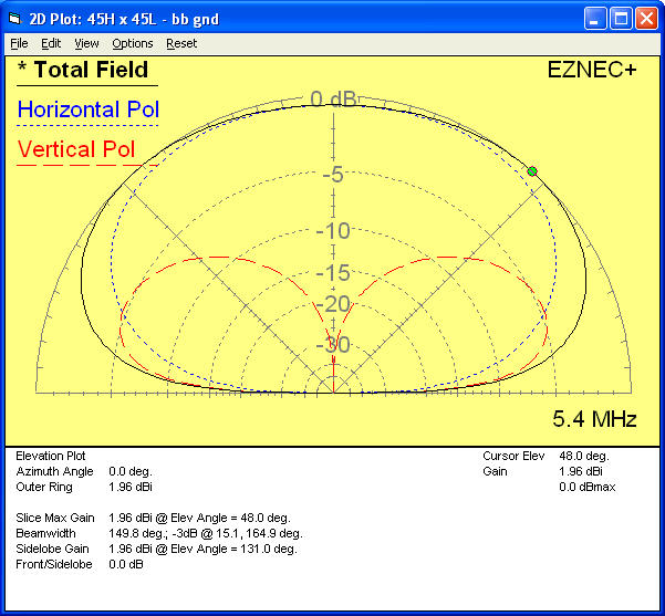
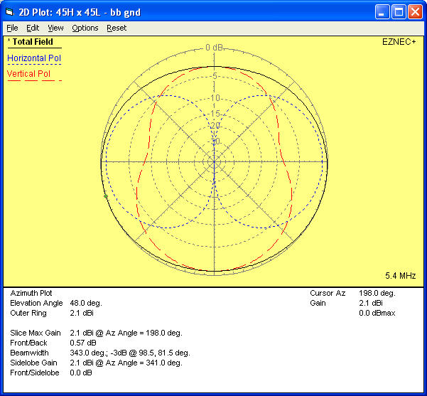
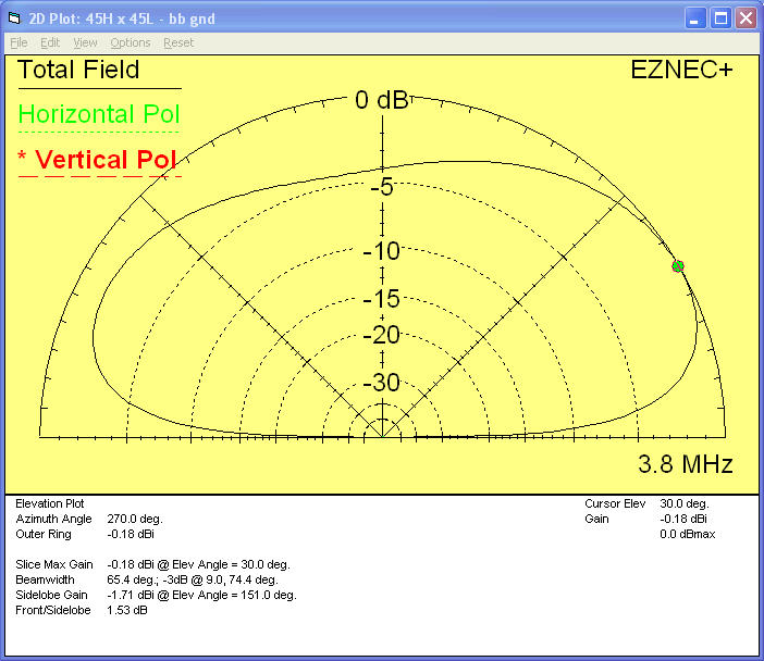
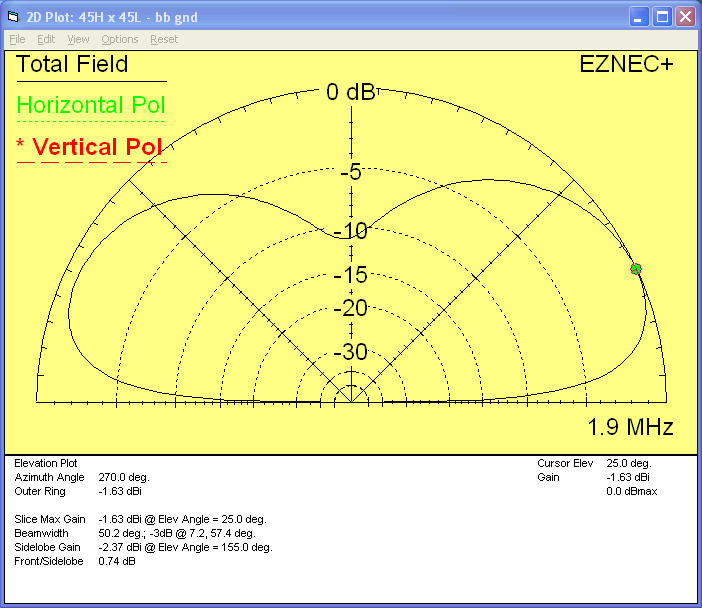
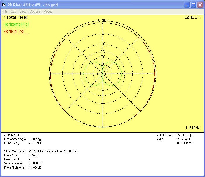
Note that the “Take Off Angle” is always at a low DX-useful angle on all bands.
On the lower bands, vertical polarization is largely responsible for good low radiation angle performance. This is the typical operation of the Inverted-L that we are familiar with, where the current maxima is largely at or near the feedpoint of the vertical section.
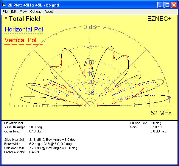
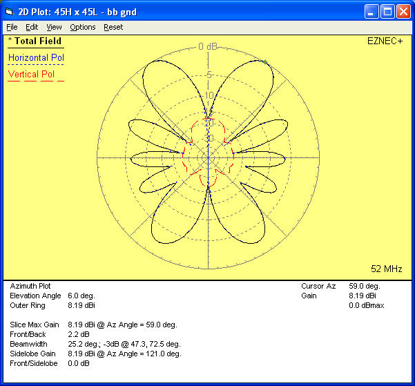
On the higher bands, horizontal polarization from the top section is largely responsible for good low angle performance. This less well known characteristic of the Inverted-L comes from the presence of current maxima on the upper horizontal section. The radiation from this upper section is that of an “end-fed” wire at the same height and of the same length, minus a few dB “radiated away” by the vertical section.
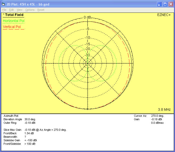
In engineering, it is often useful to look for orthogonality. Vertical polarization and Horizontal polarization are orthogonal, and can be broken out separately by antenna modeling programs like EZNec.
The maximum gain, and the Take Off Angle at the angle that is 3 dB down from the peak gain, is summarized below ===>
Below, the azimuth and elevation plots from EZNec are shown with Total Field, the Horizional Polarization component of radiation, and the Vertical Polarization component of radiation. We can see how the desirable low angle radiation transitions from vertical polarization on the low frequencies, to horizontal polarization on the higher frequencies.


Copyright – Dave Benzel – KD6RF – 2016 Dec 24
9,442 total views, 5 views today
Dave
Nice plots Dave. I’m getting ready to put up a inverted L antenna myself. It won’t be 90 feet vertical, maybe about 65 feet high. The horizontal side will slope to maybe 40 feet. I plan on using a Icom AT-120 autotuner and use antenna for muliband use. It will be cut for 160 meters. (127 feet)
Hope it works well. HF is pretty dead up here and hoping 160 works a little.
73,
Todd
AL7PX
Hi David,
I’m using a 90 foot Inverted-L, the vertical section is a aluminum tube mast 49 feet long, 1.96 inch diameter, the horizontal part consist 5 wires in cage form.
as ground screen I’m using approx 70 wires of all different lenghts the shortest is only 6feet long the longest 140 feet. Verry good antenna performing well on 60 up to 160 meteI’m using