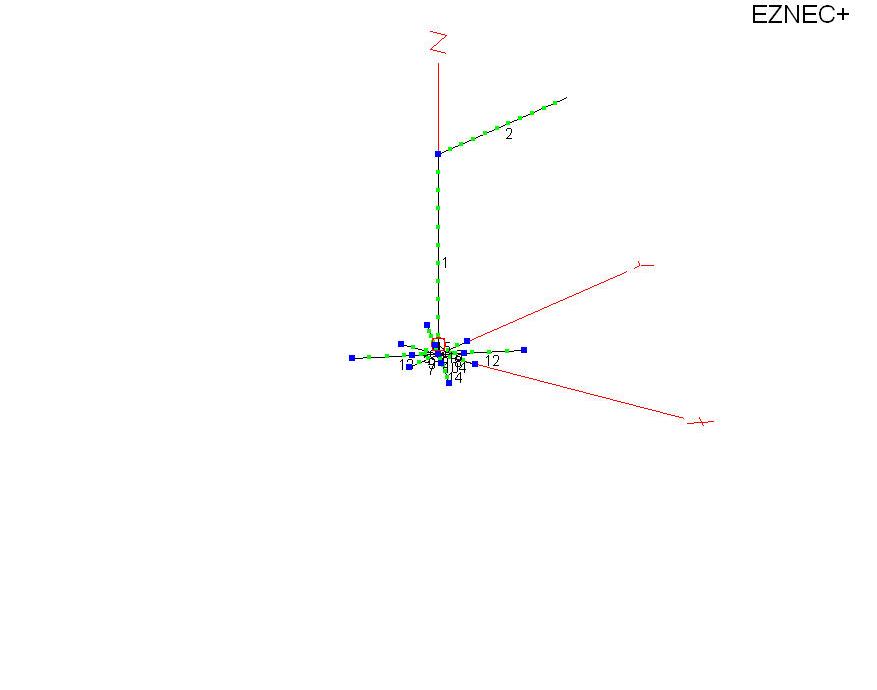
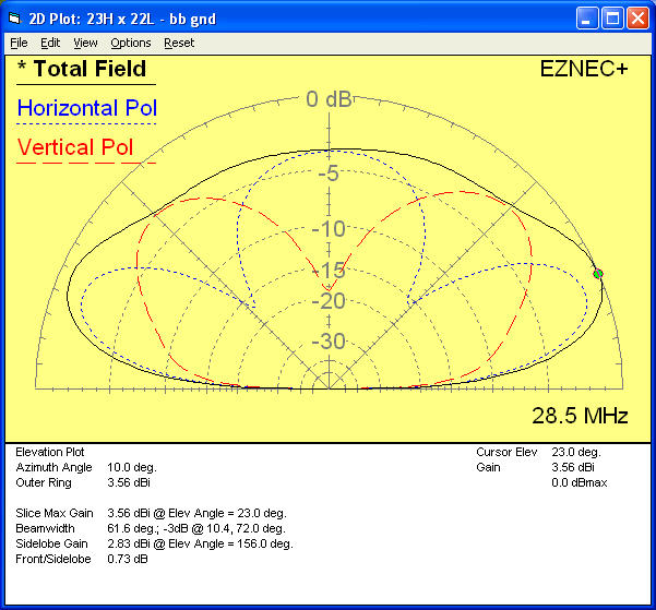
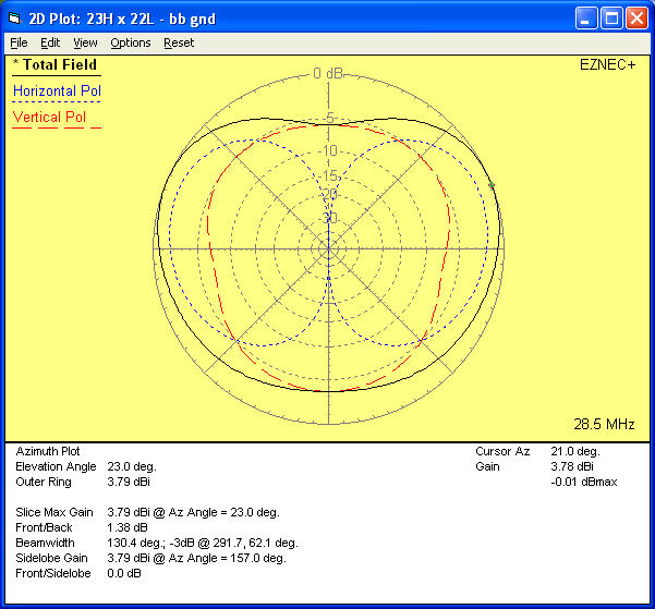
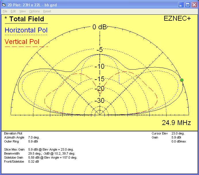
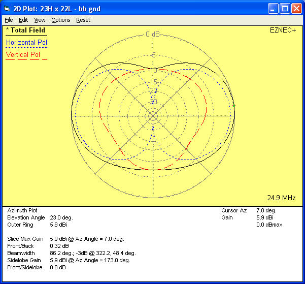
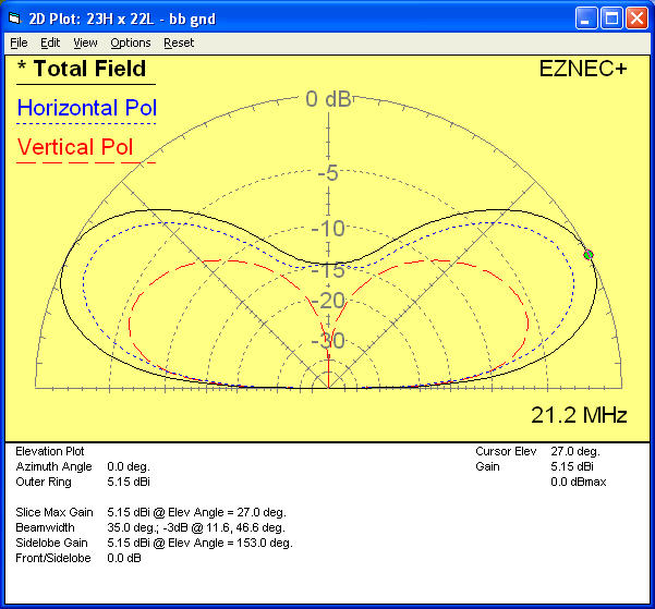
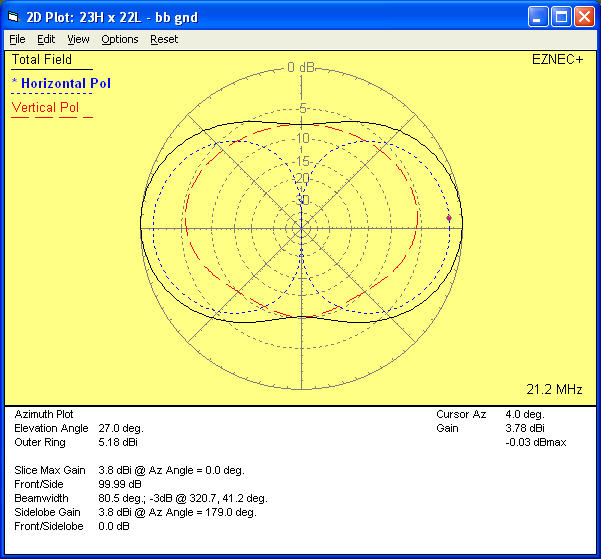
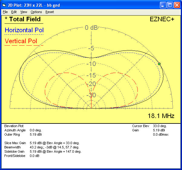
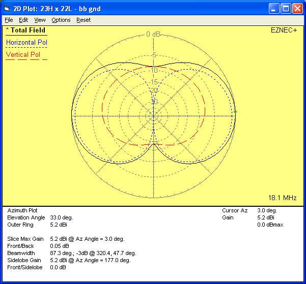
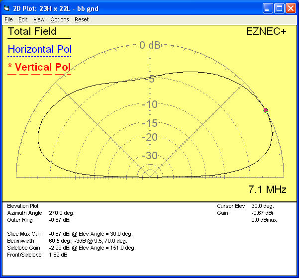
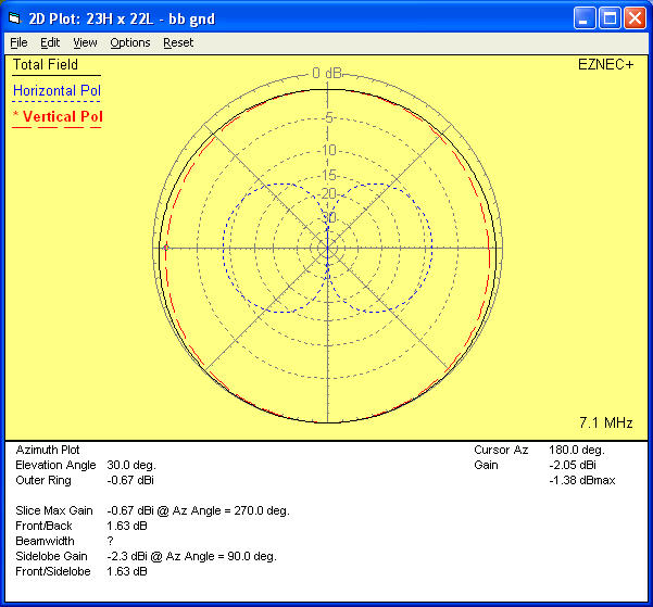
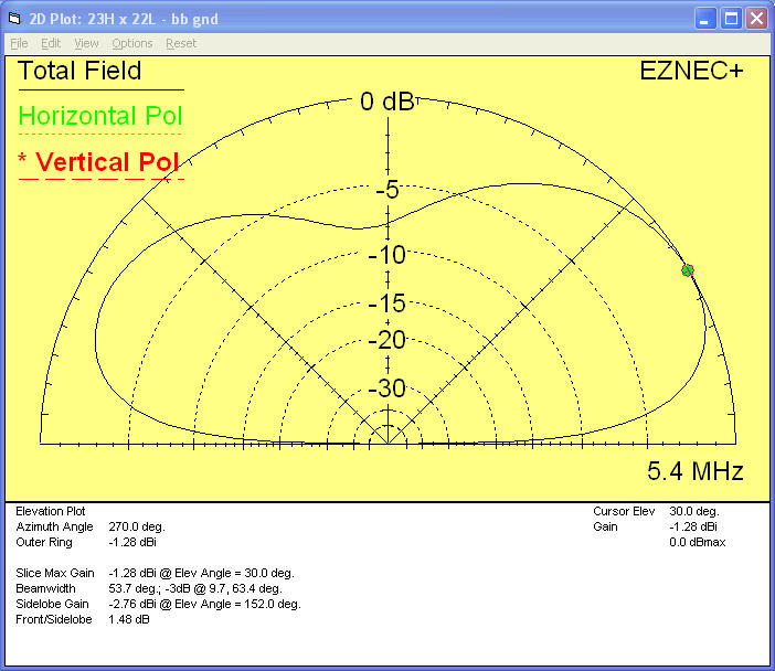
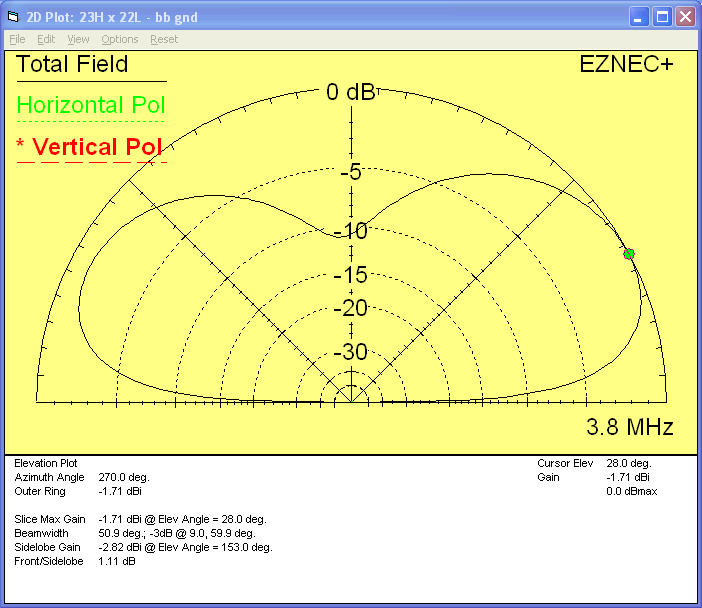
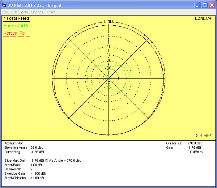
Below are presented the results of EZNec modeling of a 45 ft long End/Base-Fed Inverted-L, 23 ft high and 22 ft across. Elevation patterns and Azimuth patterns at the peak of low angle radiation are plotted for all ham bands 80 Meters through 6 Meters.
For modeling purposes, a multi-connection distributed grounded counterpoise is used. This empirical structure provides a reasonable broadband counterpoise over the frequency range of interest.
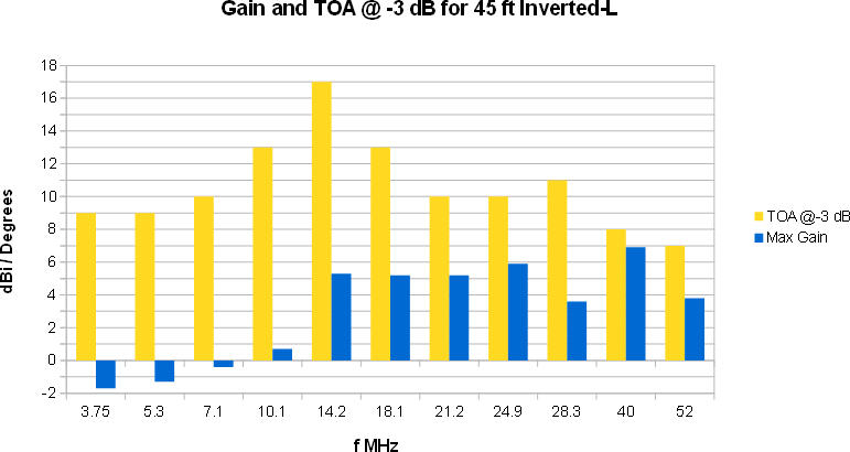
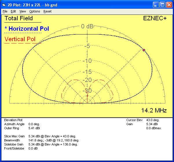
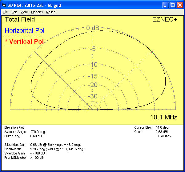
Note that the “Take Off Angle” is always at a low DX-useful angle on all bands.
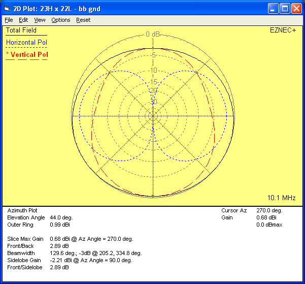
On the lower bands, vertical polarization is largely responsible for good low radiation angle performance. This is the typical operation of the Inverted-L that we are familiar with, where the current maxima is largely at or near the feedpoint of the vertical section.
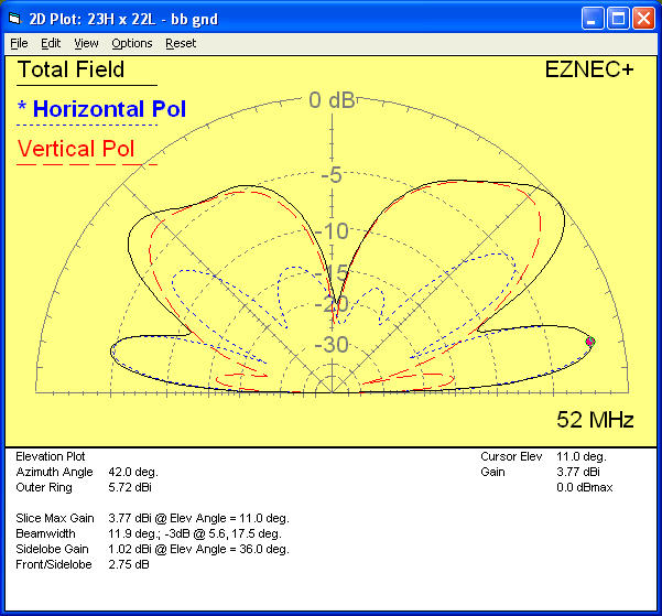
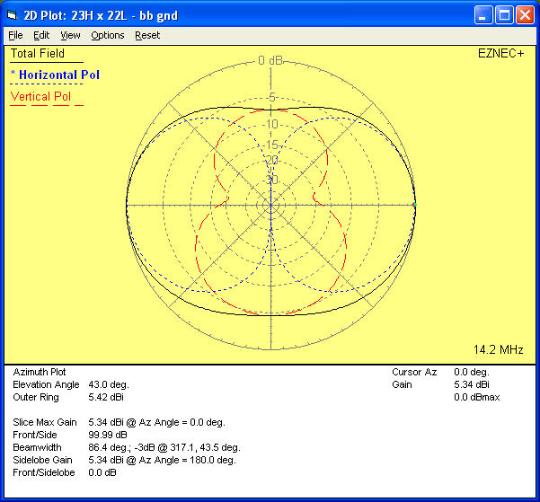
On the higher bands, horizontal polarization from the top section is largely responsible for good low angle performance. This less well known characteristic of the Inverted-L comes from the presence of current maxima on the upper horizontal section. The radiation from this upper section is that of an “end-fed” wire at the same height and of the same length, minus a few dB “radiated away” by the vertical section.
In engineering, it is often useful to look for orthogonality. Vertical polarization and Horizontal polarization are orthogonal, and can be broken out separately by antenna modeling programs like EZNec.
The maximum gain, and the Take Off Angle at the angle that is 3 dB down from the peak gain, is summarized below ===>
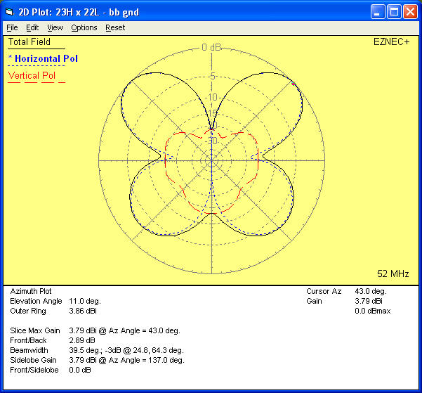
Below, the azimuth and elevation plots from EZNec are shown with Total Field, the Horizional Polarization component of radiation, and the Vertical Polarization component of radiation. We can see how the desirable low angle radiation transitions from vertical polarization on the low frequencies, to horizontal polarization on the higher frequencies.

Copyright – Dave Benzel – KD6RF – 2016 Dec 24
10,323 total views, 12 views today
Excuse my ignorance but what do you use at the feed point, I have a 85′ inverted L with 4/1 balun tunes 160 to 10 with MFJ, had CW contacts on top band but don’t think it is very efficient
Thanks
Ian
That’s a pretty nice length, but naturally efficiency depends upon how good the radial field is. As a very *rough* idea, you need around 14 or so to get decent efficiency. See the N6LF “Radial and Counterpoise” articles for better info on the subject.
Also, if the 4:1 is at the antenna base and you run coax from the 4:1 to the shack, and have the tuner in the shack, then you need to be sure the coax loss is ok as described in the “Why We Use a BMU” article.
Note that on the lowest band of 160 M, a loading coil is really what is needed, and gives lower loss than an UNUN.
I use loading coil on 160 M, and a 9:1 UNUN on the rest of the bands. A 4:1 is just fine also as there’s very little difference in loss between the 9:1 and 4:1.