Excellent technical reference article by Steve G3TXQ:
A question often asked on the Yahoo HexBeam discussion group is “what is the best height for my Hexbeam?”. It is difficult to answer the question without first understanding what the questioner means by “best”. As with any antenna, height above ground affects the tuning of the Hexbeam, its directivity and its matching; so the height which produces the lowest SWR might well be different from the height which produces best F/B or acceptable Gain.
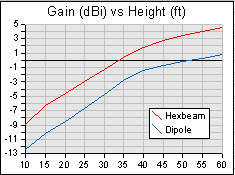
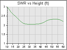
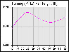
To illustrate how a Hexbeam’s performance varies with height, a 20m Classic monobander was modelled at 5ft intervals between 10ft and 60ft over Real/Average ground [Results would have followed the same trends had a Broadband Hexbeam been modelled]. The following charts show the results. Assuming that most readers will be interested in the performance of the antenna over long distance paths, the Gain and F/B figures were modelled at a 5° take-off angle. The charts can be used to predict performance on other bands by scaling the height axis accordingly; for example on 10m the height axis would run from 5ft to 30ft.


Looking at these charts in detail, we see that:
- increasing a Hexbeam’s height increases signal strength at low take-off angles; for example, lifting the antenna from 20ft to 40ft increases the signal strength by 6.4dB – over an ‘S’ Point. Although the graph “flattens” at greater heights, the signal strength continues to increase as the antenna is elevated. There is therefore no optimum height if low-angle signal strength is our criterion for “best”. Up to heights well above a hundred feet “Higher is Better”;
- by way of comparison the first chart also shows the performance of a half-wave dipole at various heights. The dipole exhibits a very similar relationship between signal strength and height; the gain of the HexBeam with respect to a Dipole at low take-off angles remains within about +/-0.5dB of its Free Space figure, whatever the height;
- the F/B ratio is surprisingly good at low heights. It decreases as the beam is lifted and then exhibits a ‘cyclic’ characteristic which is also evident in the SWR and Frequency curves. The ‘amplitude’ of this cyclic variation gradually decreases as the antenna is lifted still further, until the F/B settles at its Free Space figure of 16.2dB;
- a close look at the azimuth patterns would reveal that the high F/B figure at low heights is somewhat artificial; it results from a deep null 180° from the beam heading. However at other azimuth angles to the rear, the beam response is much higher. For example, at 10ft the 180° F/B is 24dB; but at 135° it is only 13dB. It would therefore be wrong to think that operating the beam at low heights will optimise the rejection of signals from the rear of the beam. In hindsight, plotting ‘Front-to-rear’ ratio would have been more useful, and would have painted a quite different picture;
- the SWR exhibits a similar cyclic variation with increasing height and is asymptotic to the Free Space figure of 2.25. It is worth noting just how poor the SWR is at 10ft – a height that might be convenient for tuning the HexBeam. We should expect a significant improvement in the SWR as we lift it from a low tuning height to its final position;
- interestingly, the frequency at which the beam delivers best F/B also exhibits a cyclic variation and is asymptotic to the Free Space figure of 14135 KHz. Again it is worth noting how the frequency drops quite dramatically at low heights and this needs to be taken into account if the beam is tuned at, say, 10ft.

We came to the conclusion earlier that for low-angle work ‘higher is better’ as far as Forward Gain is concerned; however this is a simplification of a more complex picture.
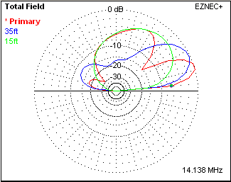
The chart on the right shows elevation plots with the HexBeam at 55ft (red), 35ft (blue) and 15ft (Green). It shows how the elevation angle of the major lobe falls as the height is increased, producing stronger signals at the take-off angles typical of DX contacts (<10°). However, for short skip work (< 1000 miles) a height of 35ft would likely deliver better performance than 55ft.
Note that above 35ft a secondary lobe begins to appear at higher elevation angles – this could be a drawback if you were troubled by strong very-short-skip QRM.
It’s also worth noting that the “best” beam pattern for you could be very specific to your operating preferences and local environment. For example, here in the UK if I had a regular sked with a DX station in central Brazil but was suffering strong European QRM, I might be interested in maximising the beam’s response at 0° azimuth / 5° elevation and minimising it at -110° azimuth / 30° elevation. Simple F/B ratio figures will not be very informative in this situation – but a 3-dimensional analysis of the beam pattern at various heights would be.
Having said all that, many Radio Amateurs will wish simply to maximise their transmitted and received signals at low take-off angles; for them “Higher really is Better!”
| Distance(miles) | Angle of Arrival |
| 500 | 40° – 70° |
| 1000 | 20° – 35° |
| 1500 | 10° – 23° |
| 2000 | 5° – 15° |
| 2500 | < 8° |
| 3000 | < 5° |
For reference, the data in this table (extracted from the ARRl Antenna Handbook) shows the relationship between Distance and “Angle of Arrival” for typical F2 layer single-hop propagation paths. But see the Hexbeam Height (Part 2) page for a much more detailed study of arrival angles and their consequences for antenna height.
2,830 total views, 2 views today