Excellent technical reference article by Steve G3TXQ:
1. Arrival angles
In “Hexbeam Height (Part 1)” we looked at how a Hexbeam’s height above ground affected its directivity and its tuning. We came to the conclusion that “higher is better” when the objective is to maximise the antenna’s performance at very low take-off angles. However, depending on our operating interests this may not be an appropriate criteria; so in this section we will look in more detail at signal arrival-angles for different HF bands and paths, and how they play against the Hexbeam’s height.

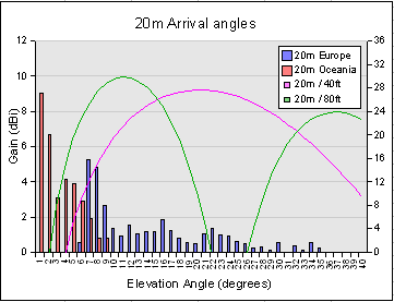
It is very simplistic to assume that signals between two fixed points are always received at the same arrival-angle. Depending on the frequency, the time of day, the season and the point in the sunspot cycle, arrival-angles can vary considerably. Usefully, the ARRL has published statistical information which predicts from ionospheric models the proportion of time that particular arrival-angles can be expected for a range of HF bands and paths, averaged over the whole 11 year sunspot cycle. Two examples are shown in the chart on the right for 20m paths between UK and Europe, and between UK and Oceania.
The red vertical bars represent the percentage of time (measured on the right hand scale) that 20m signals from Oceania will be received at particular arrival-angles. We see that the arrival-angle is never above 9°, and for a significant majority of the time the angle is below 5°. In comparison, the 20m signals from Europe (blue vertical bars) are received at much higher angles – some as high as 35° – with the majority in the range 7° to 25°.
We will now overlay on top of this statistical information the 20m elevation characteristics of a Hexbeam at two heights: 40ft (magenta line) and 80ft (green line); the left hand axis shows the antenna’s Gain in dBi. At 40ft the antenna’s vertical response shows a broad peak around 21°, making it a good “fit” for the path from UK to Europe; however at this height the antenna is at a severe disadvantage when trying to communicate between the UK and Oceania – for the vast majority of the time, signals arrive at angles where the antenna’s Gain has fallen by 6dB or more.
Looking at the antenna’s performance at 80ft we see a significant improvement for the UK to Oceania path, although the major vertical lobe is still too high in elevation to be ideal. On the UK/Europe path it’s not immediately obvious whether 80ft is any better on average than 40ft; it will perform better for angles below 16°, but it has a “null” in its response around 22° to 26°. What is clear is that on many occasions, possibly as much as 30% of the time, the antenna would be better at 40ft; this illustrates why keen contesting operators like to have a choice of antennas at different heights.

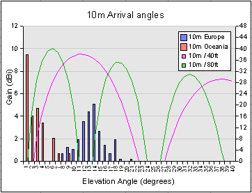
The next chart presents similar information, but for the 10m band. We see that 40ft is probably an optimum choice for the UK/Europe path, the main elevation lobe straddling the arrival-angles almost perfectly. On the other hand, 80ft would be a most unfortunate choice for this path – the null between the first and second lobes falling almost exactly at the most probable arrival-angle! Then again, 80ft is much the better choice for UK/Oceania, and higher would be better still.
Before moving on it’s worth noting that even on the UK/Oceania path it is possible for the the 40ft antenna to outperform the 80ft antenna on 10m. For about 4% of the time the arrival-angle is 9°, where the antenna at 40ft is marginally better than at 80ft. So don’t be too disappointed if a neighbouring operator occasionally gets a better long-haul DX report on his 40ft antenna than you do on your 80ft antenna – but get suspicious if it happens regularly!
2. Height Figure of Merit

Charts of the type presented above illustrate very graphically the “match” between an antenna’s vertical response and the arrival-angle statistics; however they don’t lend themselves to a quick judgement about the best height for an antenna, nor do they provide an easy way of assessing the loss in performance if we operate at other than the optimum height. I therefore devised a “figure of merit” for the height of an antenna; I take its vertical response and weight it at 1° intervals with the path stastics; the result then being averaged to provide a single number answer. It can be interpreted as the “average Gain” for an antenna at that height over that path. It’s important that the weighting be applied to linear rather than logarithmic units, so I convert from dBi to linear, then back again so that final values can be compared on a familiar scale.
Expressed mathematically:
Figure of Merit = 10.log[ ∑θ=1-90 10Gain(θ)/10.P(θ)]
where θ is the elevation angle; Gain(θ) is the antenna gain (in dBi) at elevation θ; and P(θ) is the probability of the signal arriving at angle θ, taken from the ARRL statistics.
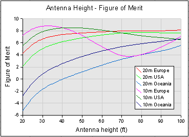
I calculated this “Height Figure of Merit” (HFOM) for a 5-band Broadband Hexbeam with baseplate heights between 20ft and 100ft, for the 20m and 10m bands, and for 3 paths from the UK: Europe, USA and Oceania. The results are shown in the chart on the right, from which we can make the following observations:
- There is no single “best height” for the antenna;
- On the long-haul UK/Oceania path there is no substitute for height. As we lift the antenna from 20ft to 100ft we get a 10dB improvement, both on 10m and 20m; and the shape of the curve suggests that more height would bring further dividends. But note that half of that 10dB improvement has been achieved in lifting the antenna from 20ft to 40ft;
- On the intermediate UK/USA path, 50ft-60ft looks to be about optimum. Anything higher produces a degradation in the 10m HFOM, and the 20m HFOM is within 1dB of its peak;
- On the short-haul UK/Europe path, the optimum height is between 30ft and 40ft. If we go much higher the 10m performance drops significantly. But notice, if we could get the antenna up to 100ft the 10m performance would recover again because the elevation of its second vertical lobe would begin to match the high arrival-angles on this path.
3. Conclusions
For those of us constrained to use a single multiband antenna mounted at a fixed and modest height, the results offer some encouragement: if we can get the antenna up around the 40ft-50ft mark we will be within 1dB of the optimum height for short-haul and medium-haul paths on all bands 20m thru 10m. And we will probably accept the “half S point” penalty that our modest height suffers on the long-haul paths.
If our antenna is presently at the 20ft mark, the effort and expense required to lift it to around 40ft looks well worthwhile; we will see improvements ranging from 1dB to 5dB, depending on the path and the band.
For the “serious” operator who is able to justify the expense and engineering challenges of lifting the antenna to 80ft or more, the results show that significant benefits will accrue on the long-haul paths; but the ability to switch to a lower antenna under certain propagation conditions becomes increasingly important, particularly at the highest frequencies.
Finally, a note of caution! The HFOM involves a weighting factor based on arrival-angle statistics. This means that, even though we may have a good average HFOM, there may still be times when the antenna performs poorly. For example, the Hexbeam at 80ft produces a reasonable HFOM of 8dBi on 20m short-haul paths. However, if at some particular instant the signals are arriving in the range 22° to 26° (which they will do over 25% of the time), we will wish we had another antenna at a different height we could switch to!
2,369 total views, 4 views today