Part 3 – We place various devices at the feedpoint of an “End-Fed” antenna without a formal “Counterpoise” – We will see why the SAME common-mode current must ALWAYS flow on the coax shield just as in Part 1.
The typical “end-fed” generally has an impedance greatly different from 50 ohms, so it is rarely fed directly with coax, as losses on the transmission line will be undesirably high for lengths of coax greater than a few 10’s of meters.
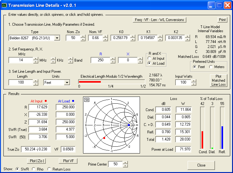
Note the high loss on several bands when a 42 ft “end-fed” is directly fed with 50 ft of RG8x coax (yellow bars)* ===>
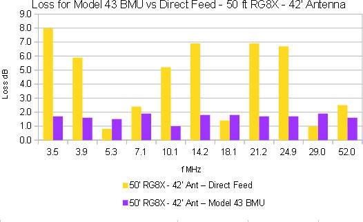
Typical solutions to this problem are Ununs and Transformers, both tuned and untuned. The mismatch extremes are mitigated, and coax losses go down, allowing much longer runs and easier matching for the tuner. Note that the loss extremes are greatly reduced with the use of an Unun (BMU) as shown in the graph above (blue bars).
It is sometimes claimed that Ununs or Transformers or Chokes, even without a formal counterpoise, isolates the feedline and reduces or eliminates common-mode current on the coax shield.
Hopefully, after reading this article, it will be clear that none of these claims are true, and that ALL of the current flowing on the “radiator” at the feedpoint ALSO flows on the coax shield in a system without a formal counterpoise. And that the current on the coax shield “counterpoise” varies along its length just like the “radiator”, and is often (always for an EFHW) LARGER than that at the feedpoint as explained in Part 2 of this series.
Again, please note that we are analyzing an “End-Fed” WITHOUT a significant Formal Counterpoise wire…
UNUNS / AUTOTRANSFORMERS AT THE FEEDPOINT
Although definitions can vary slightly, Ununs and AutoTransformers are 3-Terminal impedance transformers, where the “cold” side of the primary and secondary windings are common or are tied together. In many implementations, a portion of the secondary windings are used as the primary ===>
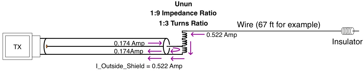
Note that the same 0.522 Amps of current must flow on the “antenna” wire, through the secondary, and common-mode on the coax shield “counterpoise” at the feedpoint just as before, in order for us to radiate the same amount of power – about 1 kW in these examples.
So we have 0.174 Amps entering the primary winding tap which exits to the inner coax shield at the bottom of the Unun or AutoTransformer. And the 0.522 Amps of “antenna” current entering the top of the Unun or AutoTransformer exits to the coax outside shield, just as KCL and common sense require.
Once matching is re-adjusted to put out the same amount of power into the new load impedance (as transformed by the 1:9 Unun), we can see that the SAME amount of common-mode current flows on the outside of the coax shield just as we saw in Part 1. And the common-mode current along the length of the coax shield also behaves just exactly as shown in Part 2 of this series.
SO-CALLED ISOLATION TRANSFORMER – UNTUNED
It is sometimes claimed that a broadband 4-Terminal transformer can be employed to reduce or eliminate common-mode currents on the coax shield. Oddly enough, this is said to be accomplished by simply not connecting anything to one of the 2 high impedance secondary winding terminals.
We use Kirchoff’s Current Law (KCL) to show that this can not be true. KCL is perfectly common sense, and says:
– We must account for ALL of the currents flowing in the circuit.
– The current ENTERING a node must equal the currents EXITING the node.
We draw the (inaccurately simplified) schematic and identify the currents and nodes ===>
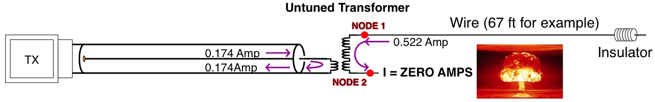
KCL is satisfied at Node 1 because the 0.522 Amps of current entering Node 1 also exits Node 1.
KCL is NOT satisfied at Node 2, and the “Isolation Transformer” claim blows up, because the 0.522 Amps of current entering Node 2 CAN NOT EXIT into an open circuit !!!
From the above, we can see that the explanations given that deny common-mode current flow on the shield simply can not be true. Yet, we know that “end-feds” radiate and make contacts just fine. Taking into account Cp, the device’s equivalent parasitic capacitance, we can see where the common-mode current flows that allows the “end-fed” to actually radiate! ===>

Once matching is re-adjusted to put out the same amount of power into the new load impedance (as transformed by the composite of Untuned Transformer and Cp), we can see that the SAME amount of common-mode current flows on the outside of the coax shield just as we saw for the case above and in Part 1. And the common-mode current along the length of the coax shield also behaves just exactly as shown in Part 2 of this series.
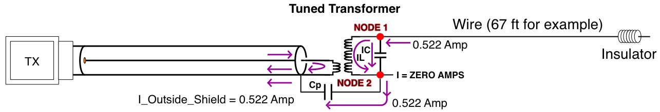
SO-CALLED ISOLATION TRANSFORMER – TUNED
Similar to above, it is sometimes claimed that a resonant L/C Tuned 4-Terminal transformer can be employed to reduce or eliminate common-mode currents on the coax shield. This is also said to be accomplished by simply not connecting anything to one of the 2 high impedance secondary winding terminals..
As above, we use KCL and we draw the (inaccurately simplified) schematic and identify the currents and nodes ===>
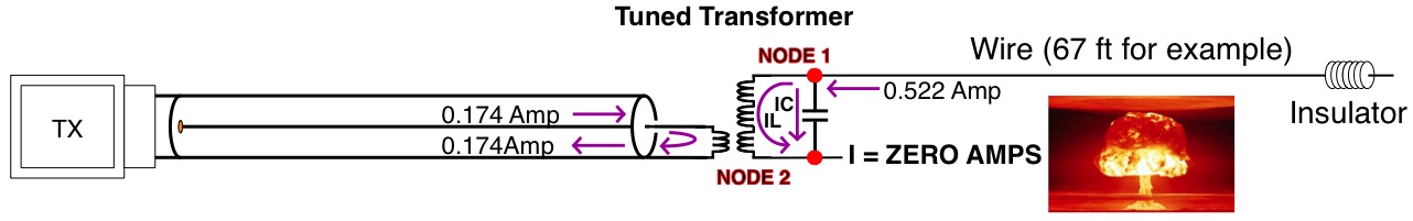
KCL is satisfied at Node 1 because the 0.522 Amps of current entering Node 1 also exits Node 1, split into IL + IC. (Note that we do not show the circulating current in order to unclutter. Since it flows in its own loop, we can safely leave it out.)
KCL is NOT satisfied at Node 2, and again the “Isolation Transformer” claim blows up, because the IL + IC = 0.522 Amps of current entering Node 2 CAN NOT EXIT into an open circuit !!!
Exactly as in the untuned case above, the common-mode current flows through the device’s equivalent parasitic capacitance Cp.
Once matching is re-adjusted to put out the same amount of power into the new load impedance (as transformed by the composite of Tuned Transformer and Cp), we can see that the SAME amount of common-mode current flows on the outside of the coax shield just as we saw for all of the cases above and in Part 1. And the common-mode current along the length of the coax shield also behaves just exactly as shown in Part 2 of this series.
LOSSLESS CHOKE AT THE FEEDPOINT
It is sometimes claimed that the fix for common-mode current on an “end-fed” without a formal counterpoise is a Choke or Balun at the feedpoint. And this sounds perfectly reasonable – after all we use Chokes and Baluns for just that purpose for other antenna types all the time with good effect.
For example, a Choke near the feedpoint of a standard dipole is usually good a idea because the high impedance of the Choke lowers common-mode current on the coax shield (the unwanted “third leg” of the dipole) by increasing current flow where it belongs – on the second dipole leg.**
But now we are talking about a formal counterpoise-less “end-fed” – there is NO other conductor where current can flow. In other words, at the outside-shield node near the feedpoint we have only 2 paths (and not 3 as in the dipole case) ===>
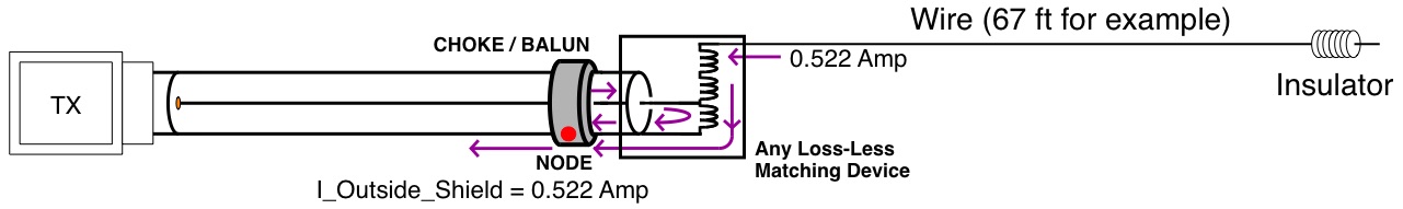
Once matching is re-adjusted to put out the same amount of power into the new load impedance (as transformed by the composite of Loss-less Matching Device and Choke Z), we can see that the SAME amount of common-mode current flows on the outside of the coax shield just as we saw for all of the cases above and in Part 1. And the common-mode current along the length of the coax shield also behaves just exactly as shown in Part 2 of this series.
(Note that in the lossy-choke case, the total current flow on the “antenna” wire is reduced to account for power dissipated in the choke. However the common-mode current on the shield is STILL the same as that on the “antenna” wire at the feedpoint.)
And we once again arrive at the conclusion illustrated by Steve AA5TB’s graphic that we saw in Part 1 of this series:
…there are NO actual counterpoise-less “end-feds”. In the absence of a formal counterpoise wire, the coax shield ALWAYS performs this function as the “other half of the antenna” via common-mode current flow.
In Part 4 of this series, we will look at real-world measurements.
________________________________TAKE AWAYS
- A Tuned Transformer, Untuned Transformer, or Unun are all effective devices for lowering the losses on the transmission line, but they do NOTHING to reduce Common-Mode Shield Currents when a formal counterpoise is not used.
- Without a formal counterpoise ALL of the current that flows on the “antenna” wire at the feedpoint also flows on the coax shield as Common-Mode Current.
- Without a formal counterpoise, the current magnitude at the feedpoint is IDENTICAL with or without a (loss-less) choke at the feedpoint, once matching is re-adjusted to put out the same amount of power into the new load impedance.
- Since current ALWAYS flows on the shield in a system without a formal counterpoise, the shield radiates, and is part of the antenna. The extent to which it radiates varies as shown in Part 2 of this series.
Dave Benzel- KD6RF – 2016 Dec 28
* Thanks to Dan AC6LA, author of several antenna related programs, for TLDetails which accurately calculates feedline loss ===> http://ac6la.com/tldetails.html
** Tom W8JI has a good article on common-mode current and choke usage with a dipole ===> http://www.w8ji.com/common_mode_current.htm
7,659 total views, 5 views today
I want to thank you for this series. It is incredible how many do not understand the simple principle that one port circuits can’t be complete circuits.
I plan to cite your write-ups when trying to educate the many who are mislead by non-scientific information that keeps getting repeated and amplified.
Regards,
Ken
K8KJG
K8KJG
Thanks Ken. Not sure why that bizarre “one terminal” circuit idea has such passion behind it. Especially when the actual principles involved are so relatively easy to understand ?!?!?