As part of renewed interest in portable medium power operations, I wanted a small cheap matcher. The units below are simply standard T-Tuners. Using dirt-cheap construction technique and commonly available parts, these units perform well at a very low cost.
 These units will handle at least 100 watts into the load impedances presented by a BMU matched 43 to 48 foot vertical, sloper, or Inverted-L. All bands are easily and efficiently matched on 80 M to 10 M ham bands. The corresponding medium power Base Matching Unit (BMU) is described here ===> http://vtenn.com/Blog/?p=1570
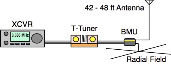
Above is the block diagram of the medium power system. Note that the BMU is placed at the Base of the antenna.
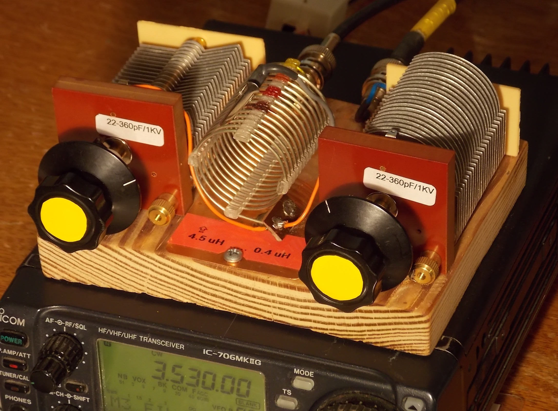
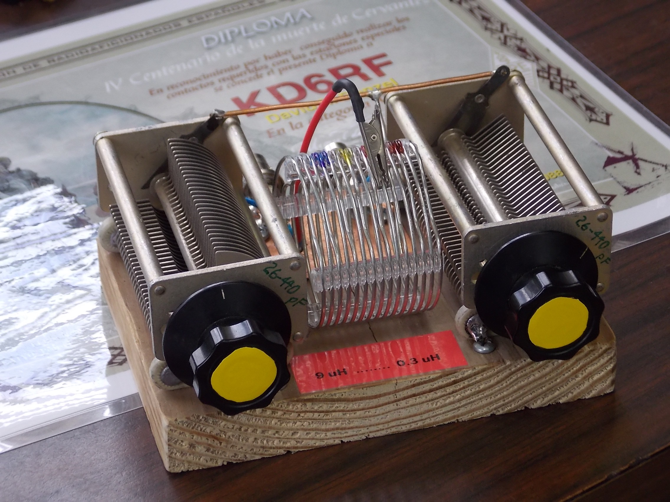
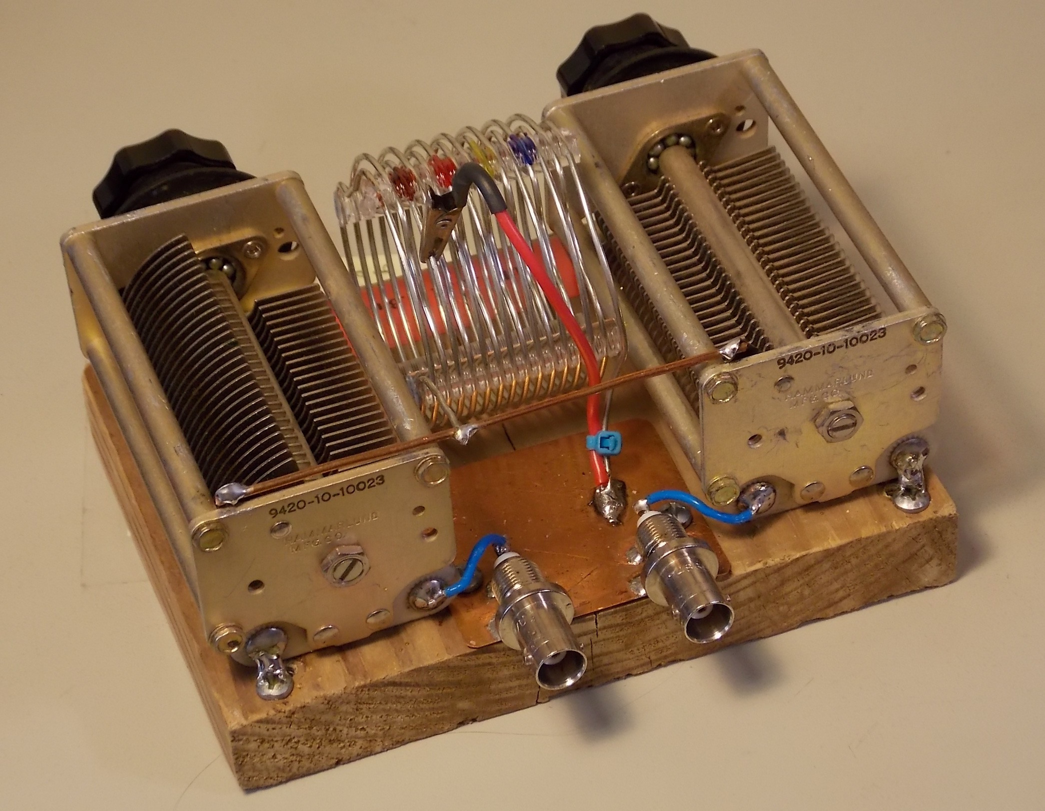
The first picture above shows the T-Tuner with new 22 – 360 pF “eBay specials” and a 4.5 uH tapped inductor. Below is the version using 20 – 440 pF surplus Hammarlund variable capacitors and an 8 uH tapped inductor:
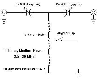
 Here is the schematic of the Medium Power T-Tuner ===>
Air core inductors were used to allow for the dirt-cheap “alligator clip” inductance selection method. Total inductance in the range of 4.5 to 8 uH is perfect for this unit to cover the 80 M to 10 M operation range.
A time of writing, the new 22 – 360 pF 1 kV variable capacitors were available on eBay at around $20 apiece. The high-quality surplus Hammarlund 20 – 420 pF units were less than $30 each from RF-Parts. Add an inductor at about $5 and your choice of connectors, and total cost for these is in the $50 to $70 range. There is no reason that even cheaper used broadcast receiver type variable capacitors couldn’t be used, and at less than $10 each.
However, note that this unit is intended for the relatively moderate load impedances presented by a 42 to 48 foot antenna with the proper BMU. If other antennas systems are used, voltages may exceed the ratings of the smaller-spaced capacitors.
CONSTRUCTION
Construction is as simple as can be. The components are attached to the insulating base by soldering them to screws sunk into the base. The BNC connectors are soldered or bracketed to the copper ground plate. The coil shorting alligator-clip wire is also soldered to the ground plate:
LOSSES
Efficiency of the unit into actual impedances presented by a BMU connected to actual antenna imnpedances was measured using the first step in the procedure shown in the article “Z-Substitution” Method for Measuring UNUN Loss Into Real-World Load Impedances”. Loss for both of the unis above was virtually identical. Since the impedance seen by the T-Tuner is a function of the length of the transmission line between the BMU and the tuner, actual loss values will vary. Losses shown below are for a short coax line of 6 feet:
80 M / 75 M: -0.20 dB
60 M: -0.85 dB
40 M: -0.85 dB
30 M: -0.33 dB
20 M: -0.98 dB
17 M: -0.60 dB
15 M: -0.77 dB
12 M: -0.38 dB
10 M: -0.37 dB
Copyright Dave Benzel- KD6RF – 2017 Mar 2
4,427 total views, 1 views today