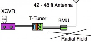
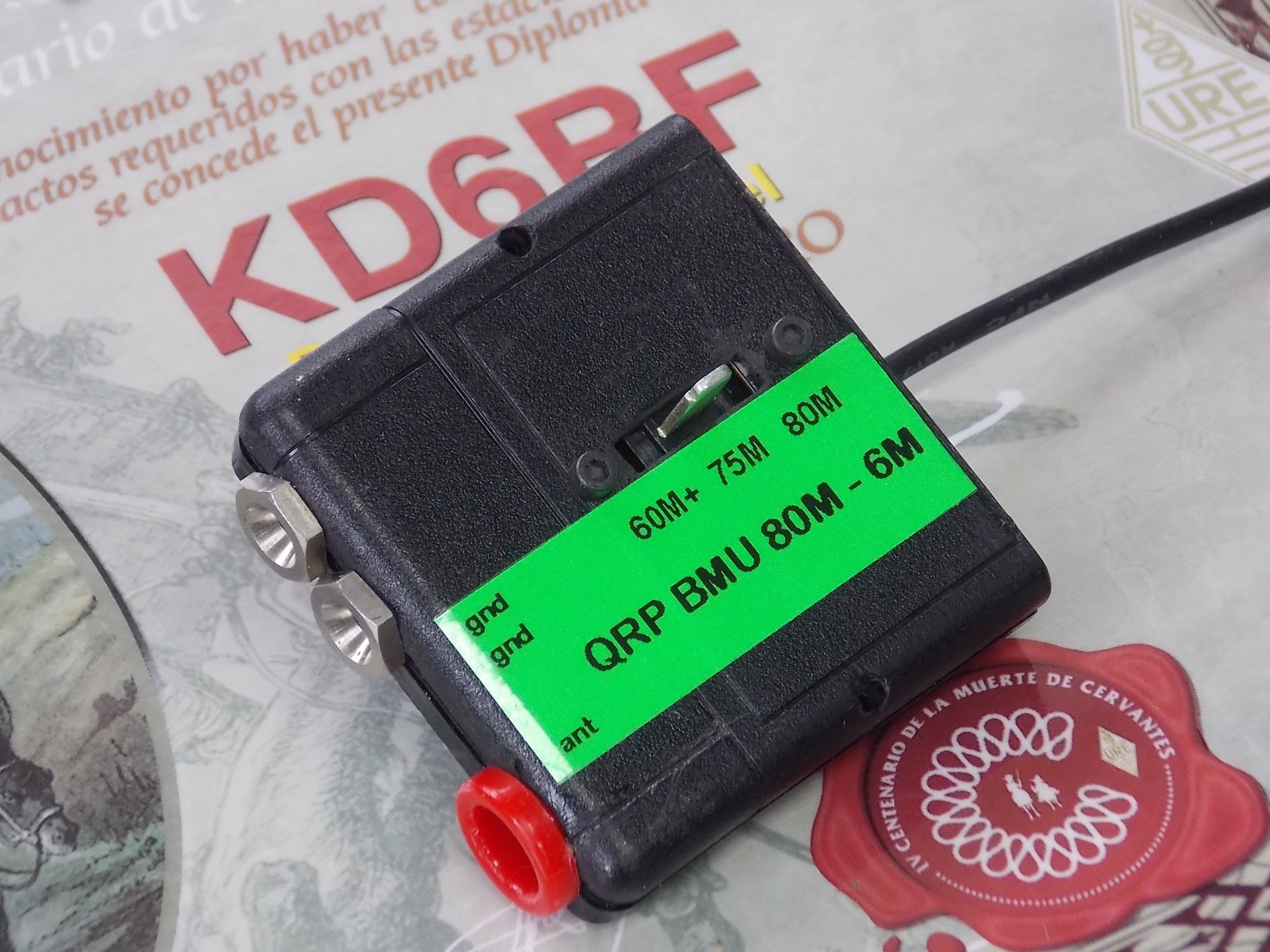
The unit on the right below is the QRP BMU (Base Matching Unit) intended for 42 foot to 48 foot vertical, sloper, or Inverted-L antennas. Naturally, these antennas (like all end-fed antennas) require a decent radial system for efficient operation on the lower bands.
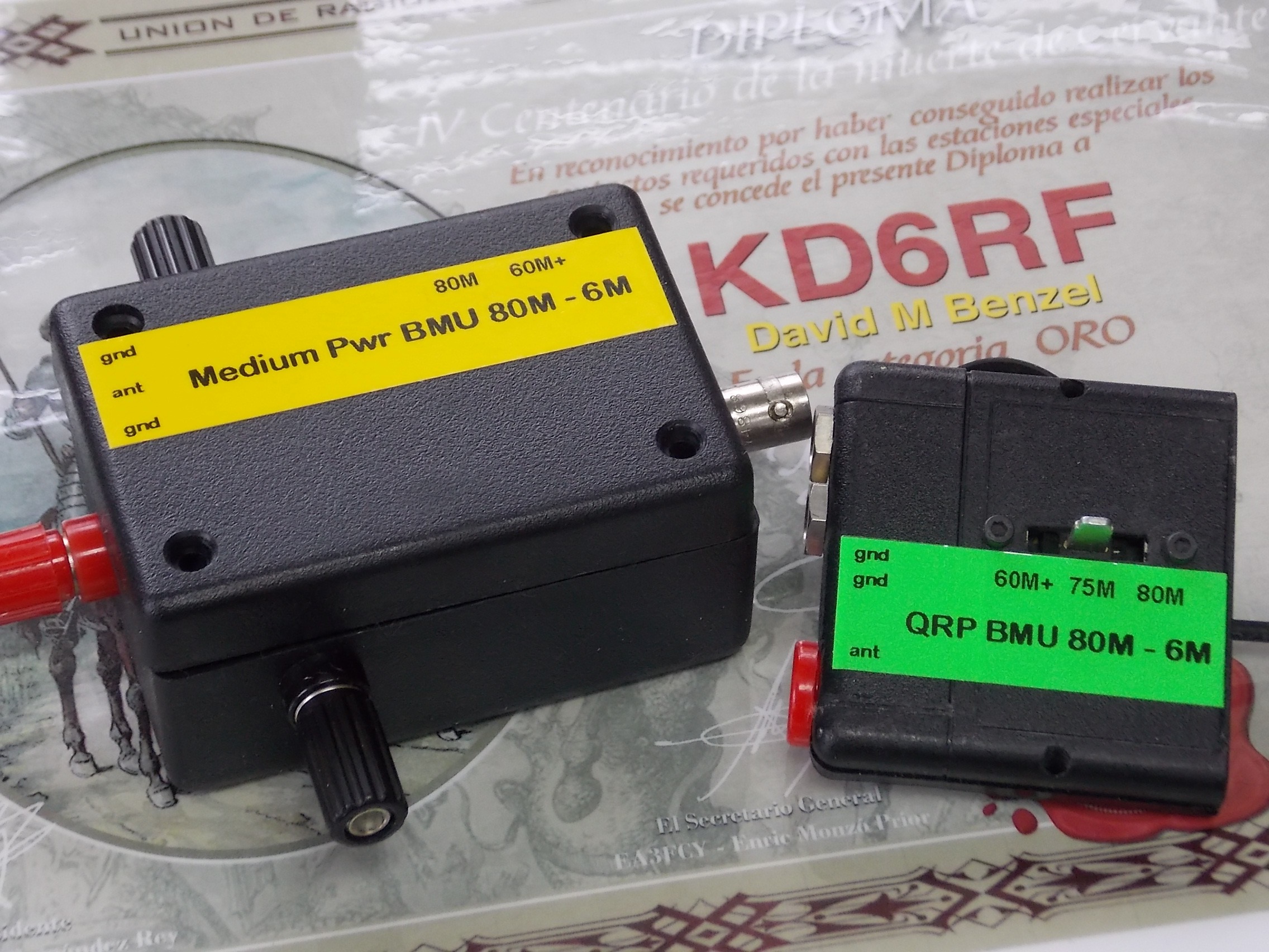 The purpose of a BMU is to mitigate the impedance extremes presented by the antenna and allows for longer low-loss coax cable runs if desired, and for low-loss matching that is within range of most tuners. To this end, we use a loading coil for 80 M / 75 M, and a 9:1 UNUN for all other bands 60 M through 6 M. More on BMUs here ===> http://vtenn.com/Blog/?p=1158.
This QRP unit can sustain at least CW 5 Watt operation (85 degree ambient temperature), and should easily sustain 25 Watts ICAS, although not tested at this level. (The QRP T-Tuner portion of this project is shown here ===> http://vtenn.com/Blog/?p=1552)
The circuitry is simple and consists of a tapped approximately 11 uH and 10 uH inductor as a loading coil for the 80 M and 75 M bands, and is switched over to a 9:1 UNUN for all other bands from 60 M on up to 6 M. (A tapped inductor is really not required as a single 10.5 uH unit provides adequate matching for the entire band.)
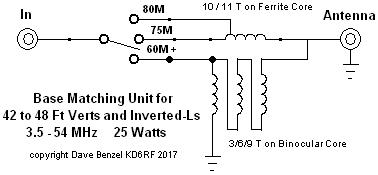
The loading coil for 80 M and 75 M is 11 and 10 turns respectively of #22 wire on a FT82-61 core. A ferrite core is used here and is of a sufficiently low loss, 0.23 dB at 75 degrees F, and physical size to handle 5 Watts continuous operation. Note: my experience is that there is a fair amount of variation in core material, and tweaking is often required to center up the SWR minimum right in the desired portions of the 80 M / 75 M band. Cores are available from standard parts suppliers like DigiKey or direct from Amidon at a few $ each.
Note the loading coil wrapped with red magnet wire right lower below:
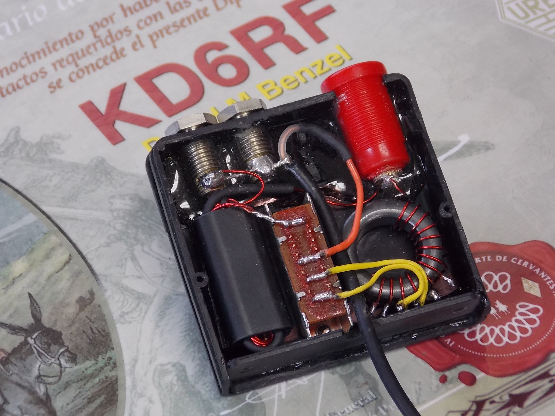 The UNUN is 9 turns tapped at 3 turns for the primary on an BN43-6802 binocular core. High permeability ferrite is used in this location as low shunt inductance is required to achieve a faithful impedance transformation. 9 turns was found to provide 640 uH shunt inductance on the secondary side, and was sufficient for 5 Watts continuous operation. (Fewer turns resulted in unacceptable heating !!!)
SMA connector is used at the input. Naturally, any connector of your choice would be fine. I chose banana jacks for the antenna and radial connections.
LOSSES
The “SWR” method and “Back-to-Back” method of UNUN characterization doesn’t tell us a lot about it’s performance into real antenna impedances, so efficiency of the unit into actual antenna impedances was measured using the procedure in the article “Z-Substitution” Method for Measuring UNUN Loss Into Real-World Load Impedances. The loss figures below are for the average impedances presented by a 43 foot antenna:
80 M / 75 M: Loading coil used, 0.14 dB
60 M: -0.74 dB
40 M: -0.42 dB
30 M: -0.66 dB
20 M: -0.95 dB
17 M: -0.43 dB
15 M: -0.80 dB
12 M: -0.80 dB
10 M: -1.30 dB
8 M: -0.33 dB
6 M: -1.35 dB
Copyright Dave Benzel- KD6RF – 2017 Mar 1
5,053 total views, 1 views today
