Apparently there are lot’s of differing opinions on antennas – now there’s a shocker ![]() Hopefully, we can put some rough numbers on things to help folks to figure out where opinion ends and basic principle begins.
Hopefully, we can put some rough numbers on things to help folks to figure out where opinion ends and basic principle begins.
After all, there’s a wide “spectrum” to draw opinion from – from just plain wrong, through propeller-headed modelers who never see the light of day, all the way up to folks who throw mega $$$ at a problem until they have the best (which is great fun, but not necessarily illuminating regarding how things actually work). And everything in between!
MEDIUM AND HIGH ANGLE GAIN
To quantify things in the eggbeater / turnstile / yagi space, a great place to start is with the series of articles on the AMSAT site “Getting Started on the Amateur Radio Satellites part III” http://www.amsat.org/wordpre…/xtra/Getting%20Started%203.pdf
As AMSAT article writer Keith KB1SF says – “For beginners on a budget, I suggest you consider some form of omnidirectional antenna.” Great advice if you want to start dirt-simple and cheap!
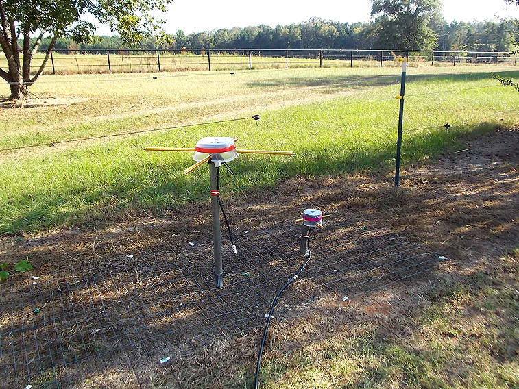
However, there are some details of implementation that we need to know about in order to design and use a solid higher-angle system – specifically, mounting the omni antennas at ground level in order to attenuate common low angle noise sources.
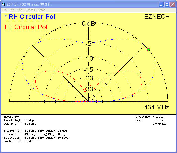
To help compare, I have attached below the gain spec for a nice turnstile design I homebrewed. We see around 3 or 4 dBc gain at down around 25 or 30 degrees or so. Another feature to note is that gain starts dropping like a rock for both systems (eggbeater and turnstile) below 20 degrees. This matches with my experience of this type of antenna being useful down to 20 or even as low as 15 degrees elevation, depending upon the satellite.
However, there is more to it than just gain!
MOUNT IT HIGH OR MOUNT IT LOW FOR BEST SNR?
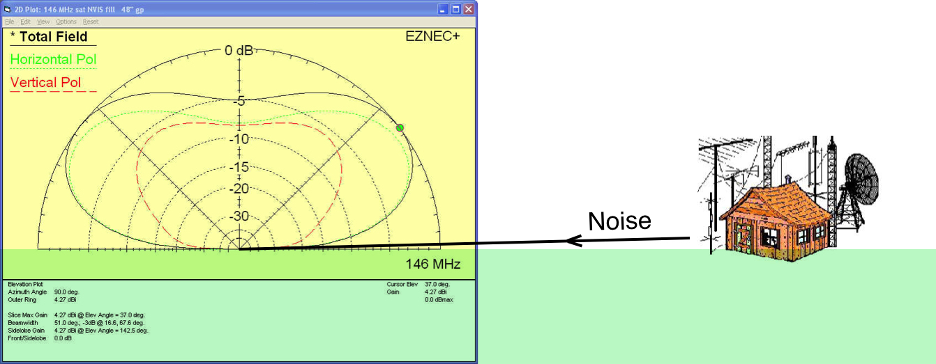
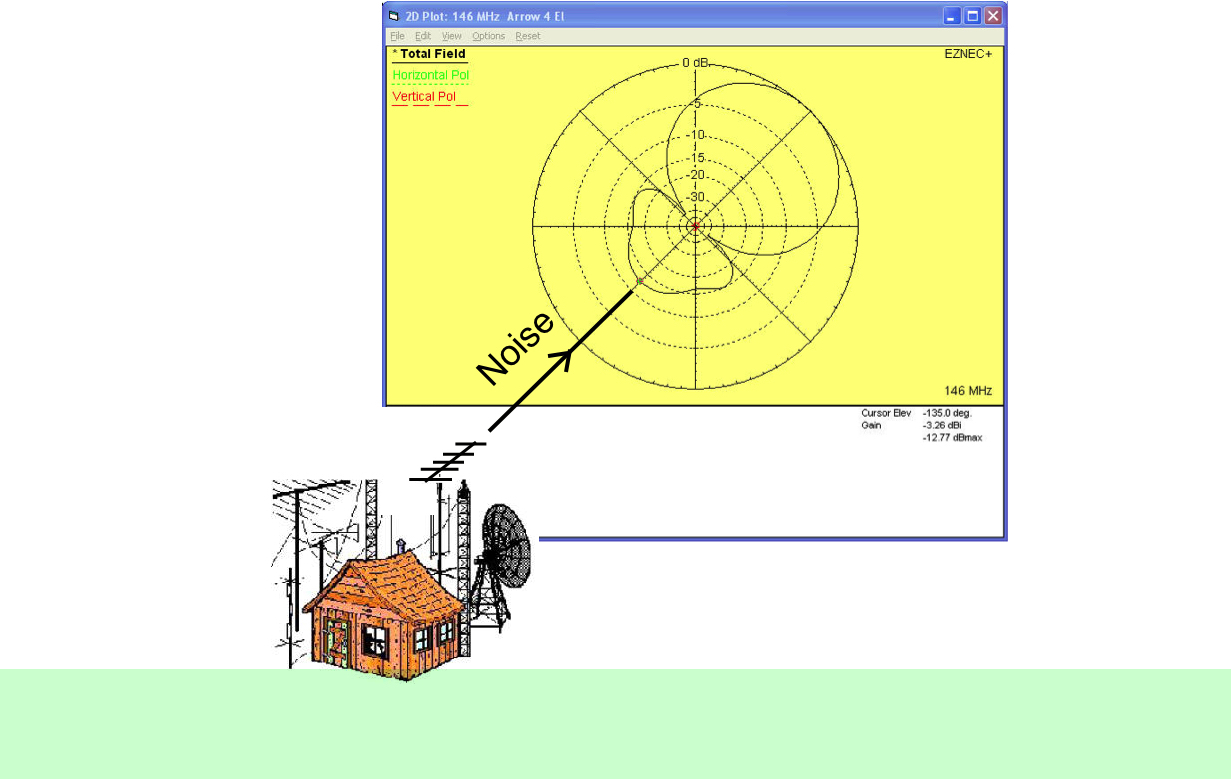
We can see that the back and side lobes of an elevated turnstile (or egg-beater, or even a yagi) can pick up noise directly from those noisy computers and other devices. This leads us to the conclusion that there is little or no advantage to using an elevated low gain antenna. Rather, we want to be able to attenuate those low angle noise sources, and therefore enhance our RX SNR. And we do that by ground level mounting our low gain turnstile antenna – to take advantage of it’s low angle attenuation.
GETTING DOWN TO LOWER ELEVATIONS
But what if one wants to get those juicy DX and grid square entities at further distances represented by elevation angles lower than 20 degrees???
Naturally, this is where real gain antennas come into play – the Arrow 3 x 7 element for example. Now Arrow doesn’t spec gains (which is refreshingly honesty!) but we can look at an “optimal” or near optimal 28 ohm 7 element design and note that gain is around 9 or 10 dBi as shown attachment below. (Note that we have dBi and dBc mixed here – how they exactly compare depends on the details of polarization and orientation).
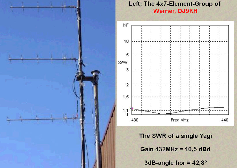
So, it’s reasonable to conclude that the typical arrow has around 6 dB greater gain than the turnstile.
WHAT DOES THIS ALL MEAN?
It means that a yagi or other gain antenna (no surprise here) is what we need to get those low elevations where distances are greater, and signal strengths are lower.
We also note that the difference in gain between yagi and turnstile at 20 or 30 degrees or so is around 6 dB – certainly significant, but often not all that important since the bird is closer and signal strengths stronger than at horizon. IOW, if one can work a sat at 1 or 2 degrees elevation with a 9 dBc antenna, it shouldn’t be surprising that one can work the same now closer sat at 20 or 30 degrees elevation with a 4 dBc antenna.
To match up distances and gains at elevation, the details of the orbit of any particular bird would need to be known, and / or measurements of actual performance (shown in a later section).
IMPORTANT ADDITIONAL CONTEXT
Although too negative regarding “omni’s” IMHO, Clayton W5PFG makes good points in regard to usage of proper power levels – specifically NOT turning up one’s own power level to make up for relatively “weak ears” due to the lower gain of the typical omni. Particularly important on weak downlink birds like SO-50. ===> https://w5pfg.us/2016/02/12/omnis-dipoles-eggbeaters-moxons-turnstiles-for-satellite-antennas/
ON-THE-AIR XW-2C DATA
Using HDSDR, satellite passes for XW-2C were recorded at 250 kB/Sec. Antennas are as above, turnstiles over ground screen. RX is the $20 RTL-SDR.COM 1 ppm device.
For the XW series of satellites, rough results show that low gain turnstile antennas can start becoming useful at around 10 degrees elevation, are “good” at around 15 degrees, and are strong at 20 or 25 degrees and above.
Uplink power started at 10 watts, and was reduced to 1 watt as the bird gained elevation. The data starts with XW-2C rise at 0 degrees and continues to set at 0 degrees. Date and time of the recorded pass is: 2017-09-10 starting at 23:55:01Z. Maximum elevation was about 65 degrees for the first recording, and about 82 degrees for the second.
XW-2C wav file ===> XW-2C wav file 708 MBytes
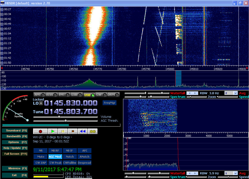
As XWing (WX-2C) pops above the horizon, it’s data and beacon become visible. Not long after at around 10 degrees, my 10 Watt CW signal in the 145.800 MHz area also becomes visible, and becomes quite strong by 12 degrees or so —
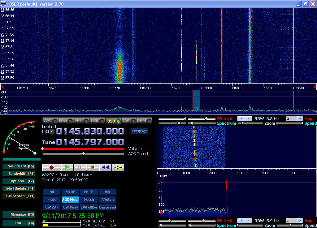
At higher elevations, signals are quite strong, even for my now 1 watt CW signal. The sat’s beacon is visible around 145.791, and we see WB4FWQ calling CQ on SSB —
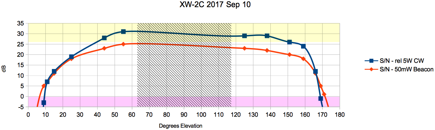
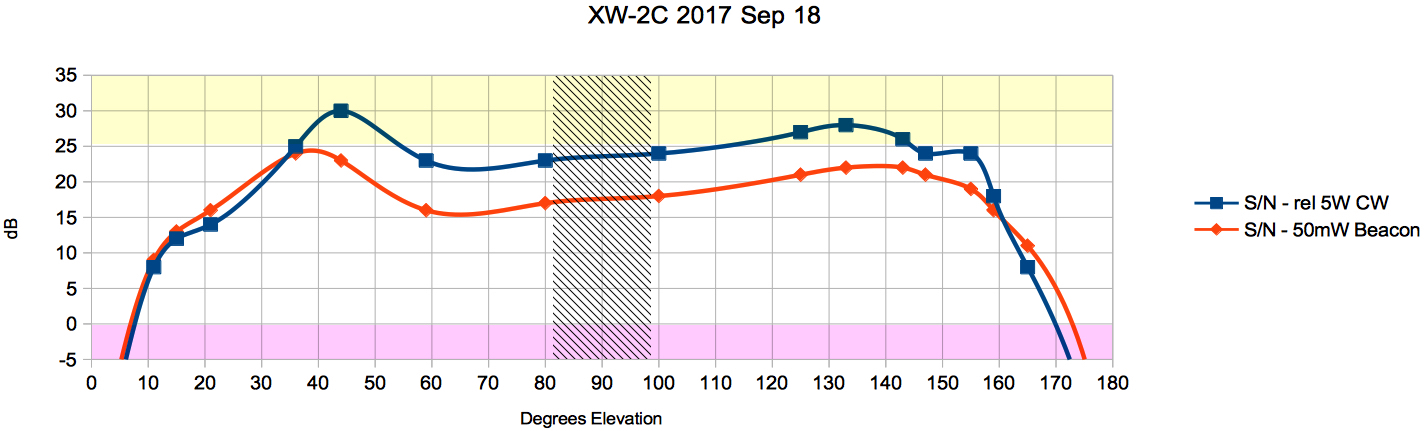
Below are graphs of performance for 2 XW-2C passes – 0 dB defined as minimum SNR for readable CW in a 350 Hz Bandwidth. Graphs normalized to 5 Watt uplink power and CW with the ground-mounted turnstile antennas described above. Naturally, these numbers are also relative to the local noise floor.
IOW, add 3 dB if you are using 10 Watts instead of 5, subtract about 8 dB if you are using SSB rather than CW…
Red region is unreadable, yellow region is where one should consider lower uplink power.
ON-THE-AIR AO-7 DATA
For the venerable old AO-7 satellite, rough results show that low gain turnstile antennas start becoming useful to get in at around 20 or 25 degrees. Other passes show much stronger signals, perhaps due to AO-7 illumination
Uplink power started at 10 watts, and was reduced to 1 watt as the bird gained elevation. The data starts with AO-7 above horizon at 10 degrees and continues to 10 degrees before set. Date and time of the recorded pass is: 2017-09-11 starting at 10:28:58Z. Maximum elevation was also about 65 degrees.
AO-7 wav file ===> AO-7 wav file 972 MBytes
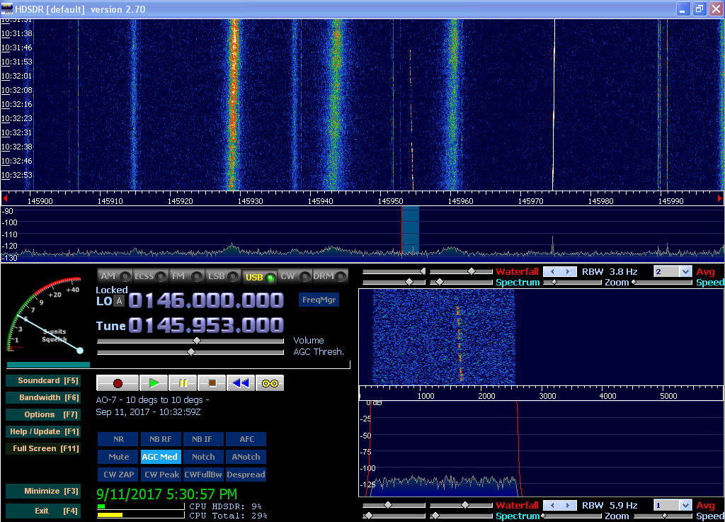
As AO-7 rises, my 10 Watt CW signal in the 145.950 MHz area becomes visible at around 20 degrees, and becomes fairly strong by 30 degrees or so. What probablt once was the sat’s beacon appears at around 145.972 MHz. Also quite visible are the 3 “noise bands” associated with the AO-7 downlink —
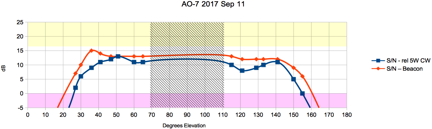
0 dB defined as minimum SNR for readable CW in a 350 Hz Bandwidth. Graphs normalized to 5 Watt uplink power and CW with the ground-mounted turnstile antennas described above. Naturally, these numbers are also relative to the local noise floor.
IOW, add 3 dB if you are using 10 Watts instead of 5, subtract about 8 dB if you are using SSB rather than CW…
Red region is unreadable, yellow region is where one should consider lower uplink power.
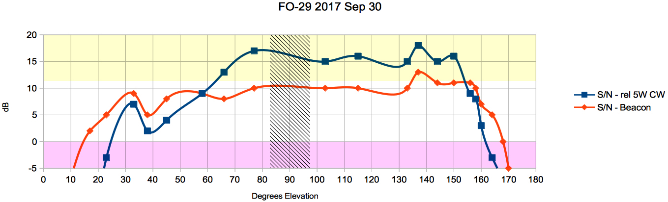
ON-THE-AIR FO-29 DATA
For FO-29, rough results show that low gain turnstile antennas start becoming useful at around 20 to 40 degrees elevation, with some assymetry.
Uplink power started at 10 watts, and was reduced to 1 watt as the bird gained elevation. The data starts with FO-29 above horizon at 5 degrees and continues to 5 degrees before set. Date and time of the recorded pass is: 2017-09-30 starting at 14:41:24Z. Maximum elevation was also about 65 degrees.
FO-29 wav file ===> FO-29 wav file 766 MBytes
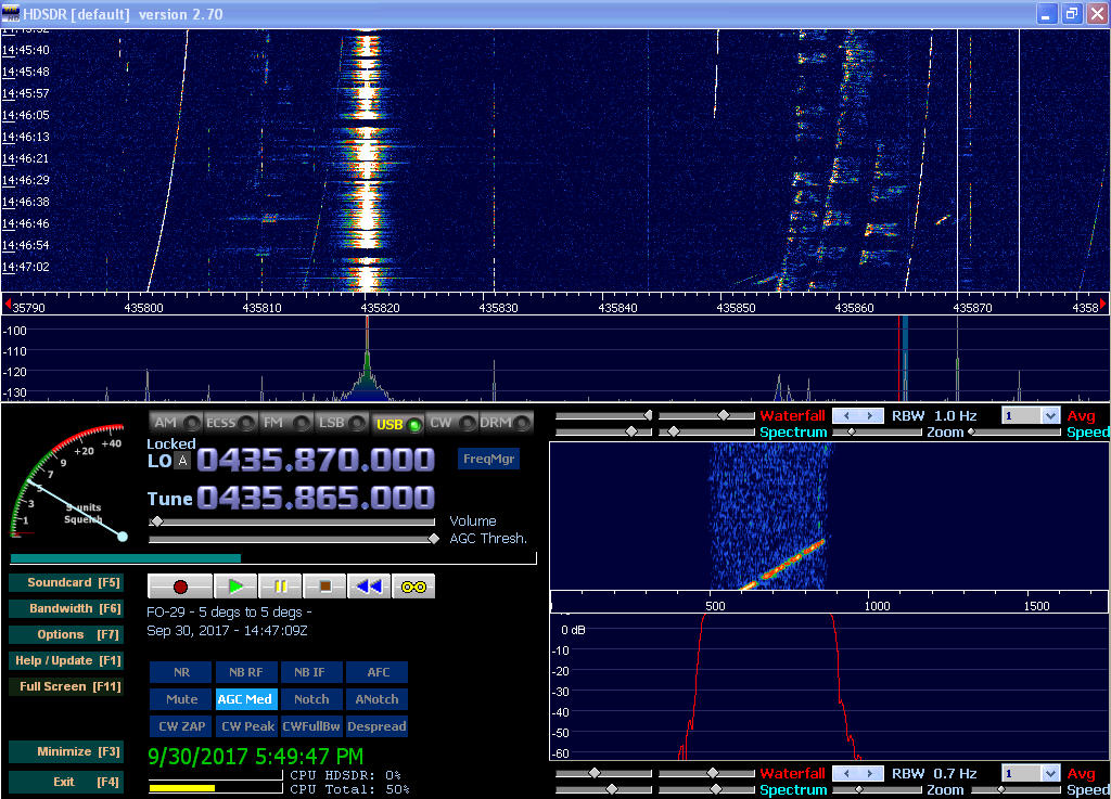
On FO-29 we see some very workable SSB signals as well as my CW signal in the 435.865 MHz area. The strong signal at 435.820 is a harmonic or spur from the 2 M TX. Also visible is the sat’s beacon at around 435.802 MHz.
FO-29 response was not very symmetrical for reasons unknown. It can be consider good signals at roughly 40 degrees as rising from the south to about 20 degrees as it sets to the north.
As with the other sats above, 0 dB defined as minimum SNR for readable CW in a 350 Hz Bandwidth. Graphs normalized to 5 Watt uplink power and CW with the ground-mounted turnstile antennas described above. Naturally, these numbers are also relative to the local noise floor.
IOW, add 3 dB if you are using 10 Watts instead of 5, subtract about 8 dB if you are using SSB rather than CW…
Red region is unreadable, yellow region is where one should consider lower uplink power.
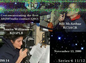
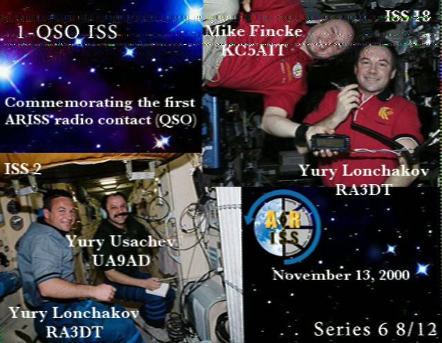
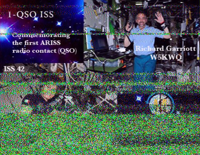
ON-THE-AIR ISS DATA
Received SSTV images from 2016 ISS event, from / to approximately 15 degrees.

ON-THE-AIR AO-85 DATA
Received images from experimenters Wednesday”, 2017 Jul 29.

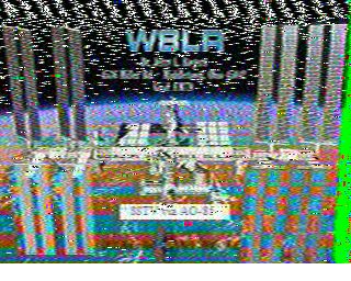
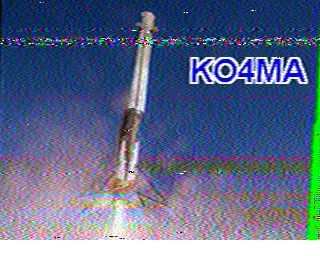
Here is an image posted by KO4MA – the same image as mine, 2 above ……….

Note how KO4MA’s reception of W8LR’s image is much noisier than mine using my low gain omni. This illustrates nicely how a low gain antenna in a low noise location (i.e. ground mounted) can outperform other systems in some circumstances.
It ALSO illustrates the folly of using “anecdotal stories” to generalize about antenna performance. If one were to go simply by the superior performance of the low-gain ground-mounted turnstile on that one picture above vs. KO4MA’s system, one would conclude that the turnstile was “The Superior Antenna” in all cases. And one would be Completely Wrong!!!! There is no doubt that a high gain yagi system will outperform the low gain omni system in MOST cases. This data ALSO shows that a well design low-gain turnstile can perform well (even superior in some limited number of situations) compared to a higher gan yagi system.
Copyright Dave Benzel- KD6RF – 2017 Mar 2
7,540 total views, 2 views today