Out here in beautiful rural East Texas, the noise levels on the HF bands are not too awful bad – IF you have a decent noise limiter or blanker.
We have some nasty short spike shortwave noise at a 33 mSec rep rate. It may be electric fences? our cable system?, but I have not tracked it down yet since I did not even know it existed due to modern receiver’s good noise blankers. (This explains the picket-fence spectrum of certain frequency ranges on the IF waterfall display).
Most of my classic radios have a noise limiter that works pretty well – but this old SX-16 does NOT have one. And trying to SWL around can be very annoying.
I though about putting in the SX-17 noise limiter circuitry, but it’s a fair amount of re-wiring and hole punching for the new tube, and generally quite a chore. Instead I decided to design and try a simplified version of the Hallicrafters SX-17 ANL, but built on a homebrew “hybrid” of small resistors, capacitors, and some silicon diodes. The “hybrid” is simply tacked into the existing un-modified SX-16 circuitry. It is the greenish drab rectangle slightly left of center in the pic below:
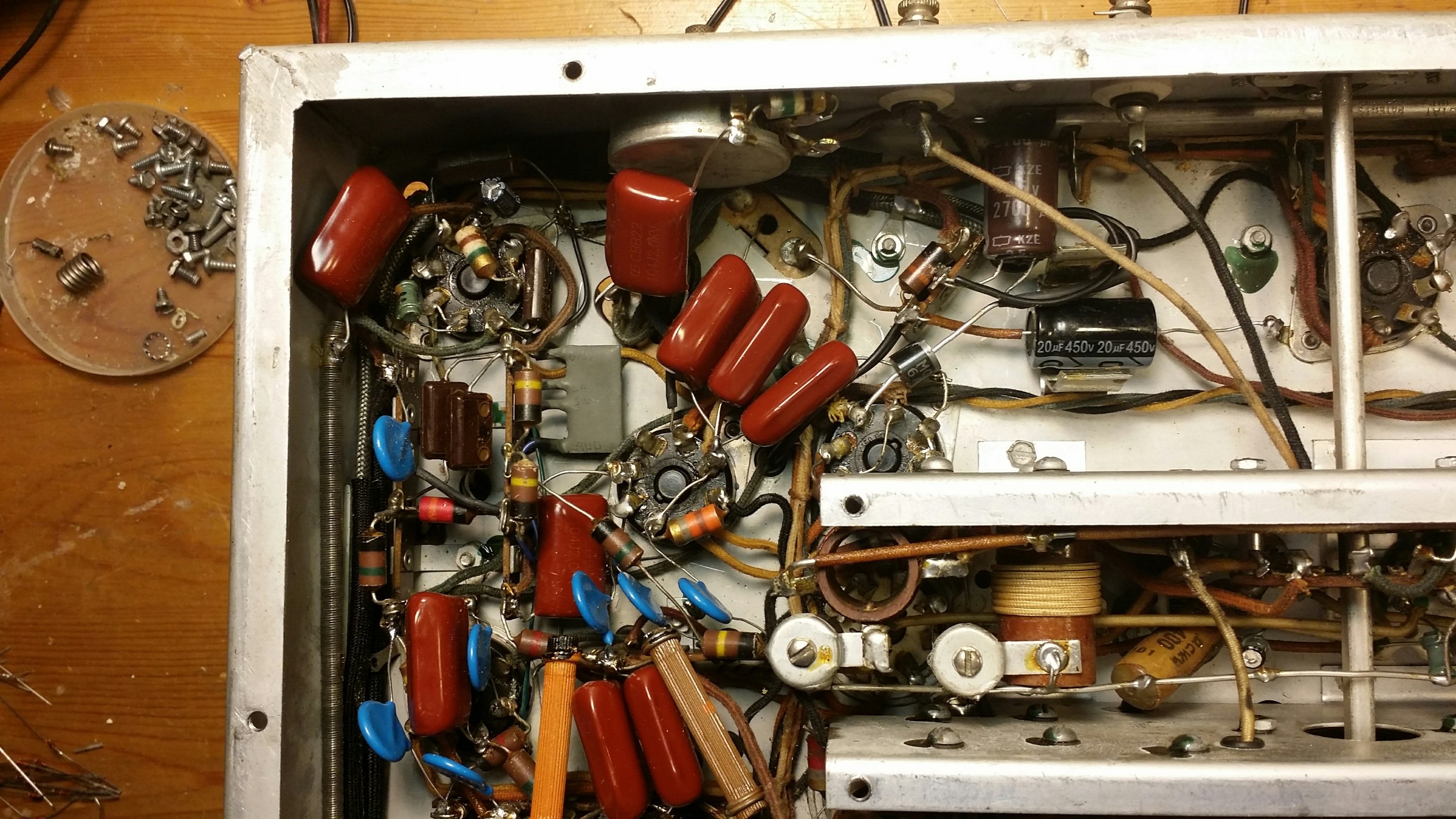
The “hybrid” is just small R’s, C, diodes and the 4 connecting wires soldered on a prototyping card, smoothly covered in epoxy, and painted.
This circuit uses similar key circuit values and time constants to the SX-17 noise limiter, and was tweeked by ear to make sure it performed well. By oscilloscope and by ear, I made sure that the new circuit did not introduce any major distortion or other problems.
As an aid to understanding what Hallicrafters did for their AVC and ANL circuitry, I re-drew the relevant bits from the rats-nest schematics found in the manuals. I omitted some small value capacitors as they seen not to aid in the understanding of how these negative-peak shunt limiters/clippers work. (It may help understanding to note that the right-most wire is bypassed to ground through a 10 uF capacitor, and is at AC ground).
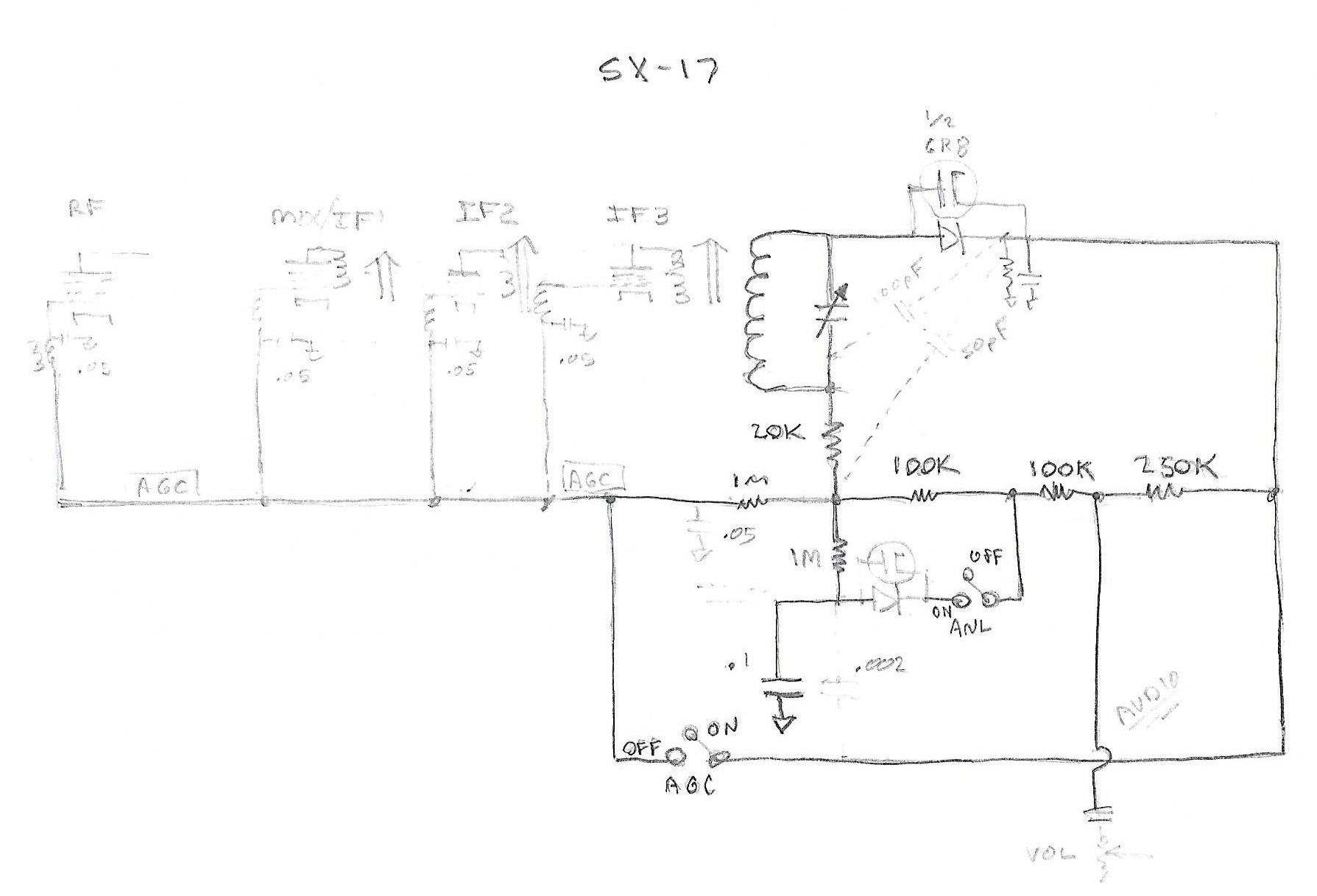
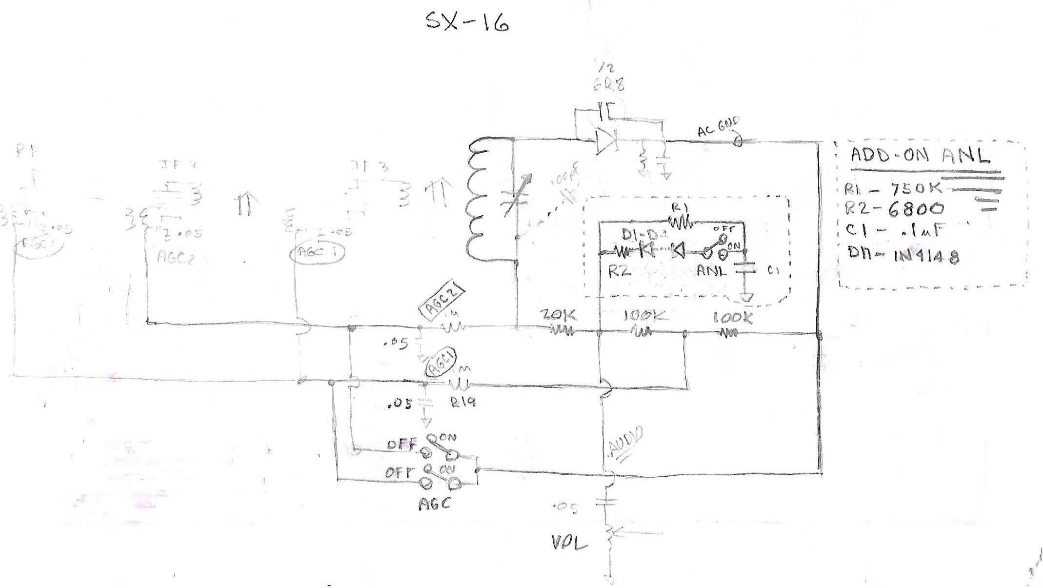
You can see that the new circuit generates a roughly AVC level voltage on C1 through R1, which is roughly the voltage level that the diode clipper works against. This clips off the giant negative-going noise spikes, preventing them from overwhelming the audio going to the top of the volume control.
The new ANL circuit’s 4x series silicon diodes allows around 3 volts of negative audio swing (underneath the average level of the AVC) before soft clipping action starts taking place. R2 provides “softer” clipping action, and prevents C1 from charging up too much via the noise spikes themselves. These values provided nicely noise-limited audio with little distortion of the desired audio waveform.
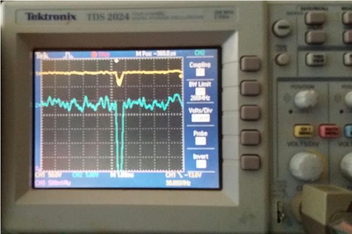
Before ANL:
After ANL circuit added.

It’s worth noting that there is some visible even order distortion/clipping on loud negative-going audio peaks (although I’ll be darned if I can hear much difference), but you can see the previously horrible noise spike is tamed and greatly attenuated.
copyright Dave KD6RF
3,235 total views, 1 views today